Optical field modulation for phase imaging: A unified framework for interferometric and diffractive strategies

*Correspondence to:
Yikang He, School of Information Science and Engineering, Shandong University, Qingdao 266237, Shandong, China.
E-mail: yikang.he@sdu.edu.cn
Light Manip Appl. 2026;1:202614. 10.70401/lma.2026.0018
Received: June 05, 2026Accepted: August 25, 2026Published: August 25, 2026
Abstract
Compared with conventional intensity imaging, complex optical field imaging enables the recovery of both amplitude and phase information of the optical field, and has become an important tool in label-free microscopy, surface metrology, and crystal characterization. However, because conventional detectors can only measure intensity and cannot directly record phase, complex field reconstruction is an ill-posed inverse problem that heavily relies on physical constraints and computational priors. Optical field modulation offers an effective solution by imposing known, controllable modulations into the illumination, propagation, reference, or detection path, improving the observability and recoverability of phase information. Optical field modulation increases the measurement diversity and improves the solvability of the inverse problem, reducing reconstruction ambiguity and improving robustness to noise and missing data. This review establishes a unified framework that classifies optical-field modulation according to the measurement mechanism and modulation location, and compares different strategies in terms of information diversity, identifiability, acquisition efficiency, calibration burden, and dynamic adaptability.
Keywords
Optical-field modulation, phase imaging, quantitative phase imaging, phase retrieval
1. Introduction
In wave optics, an optical field is described by a complex amplitude containing both amplitude and phase information[1,2]. Conventional image sensors, however, directly record only intensity and therefore discard the phase of the field. This missing phase is not a minor loss of information: it encodes optical path length, refractive-index variation, surface height, and lattice displacement, which are central to label-free biological microscopy[1,3,4], optical metrology[5-7], and crystal or nanoscale material characterization[8-10]. Early phase-contrast methods, represented by Zernike phase-contrast microscopy, converted phase variations into visible intensity contrast and greatly advanced the observation of transparent specimens[11]. However, such methods are mainly qualitative and do not directly provide quantitative phase or full complex-field information.
Quantitative phase imaging (QPI), digital holography, and phase-retrieval methods were developed to recover phase or complex-amplitude information from measurable optical data[1,12,13]. Interferometric approaches encode phase through interference between an object field and a reference or self-reference field, as in off-axis digital holographic microscopy, diffraction phase microscopy (DPM), and spatial light interference microscopy[12,14,15]. Diffractive and intensity-only approaches instead recover phase computationally from propagated intensity images or diffraction patterns, as in transport-of-intensity imaging, coherent diffraction imaging (CDI), ptychography, and Fourier ptychographic microscopy (FPM)[13,16-19]. These two routes have different strengths. Interferometric methods provide direct and sensitive phase access, but they require stable interference, accurate alignment, and reliable separation of the zero-order and conjugate-image terms[20-22]. Diffractive methods avoid an explicit reference beam and can support compact, lensless, and short-wavelength imaging[23-25], but their inverse problems are often under-constrained and sensitive to noise, initialization, sampling diversity, and model mismatch[13,18].
Optical-field modulation has become a central strategy for addressing these limitations. In this review, optical-field modulation refers to the deliberate control of the illumination, propagation path, reference wave, aperture or Fourier plane, wavefront, scattering medium, or detection-side coding element before intensity measurement. These operations do more than add auxiliary optical components. They reshape the forward imaging model by changing how object phase is transferred into measurable intensity variation. Phase shifting and spatial-carrier modulation separate interference terms in holography[20-22]; angular and structured illumination expand spatial-frequency coverage or improve phase contrast[19,26,27]; and axial or wavelength-dependent diversity provides additional propagation constraints[28-30]. Spatially partially coherent illumination has also been used for diffractive phase imaging[31], and engineered coherence structures provide an additional degree of freedom for controlling source coherence[32-34] and propagation stability, such as beam-wander suppression[35]. Coded masks, coherent modulators, and sensor-integrated structures further encode otherwise inaccessible spatial-frequency or phase information into recorded intensities[36-39]. The common purpose is to convert the ill-posed phase-recovery problem into a better constrained optical-computational inverse problem.
Although many modulation-enabled phase-imaging methods have been reported, the field is still difficult to navigate. Existing studies often emphasize individual optical layouts or reconstruction algorithms; however, the relationships among modulation location, information diversity, reconstruction strategy, and application boundaries have not been systematically compared. For example, phase shifting, off-axis carrier encoding, ptychographic scanning, Fourier-ptychographic angular illumination, coherent modulation imaging (CMI), speckle coding, and sensor-integrated coding all improve phase observability, but they do so with different trade-offs in spatial resolution, field of view (FOV), signal-to-noise ratio, acquisition speed, photon efficiency, hardware complexity, calibration burden, and suitability for dynamic imaging[40-43]. Without a comparative framework, it is difficult for readers to select an appropriate modulation strategy or to identify which bottlenecks remain intrinsic to each class of method.
This review therefore examines optical-field modulation as a unifying framework for interferometric phase measurement and diffractive phase retrieval. We first summarize the basic measurement principles of interferometric and diffractive phase recovery, then classify modulation strategies according to where they act in the imaging chain: illumination-side modulation, propagation and diversity modulation, reference-wave and interference-term modulation, aperture or Fourier-plane modulation, and detection-side or sensor-integrated modulation. For each class, we discuss not only representative implementations, but also the physical diversity introduced, the corresponding reconstruction model, and the practical trade-offs in speed, robustness, calibration, and system complexity. We then compare representative modulation-enabled methods at the system level and develop an application-oriented framework for method selection. Finally, we discuss emerging opportunities in low-photon and low-dose imaging[44-48], polarization-resolved and vectorial modulation[49-52], ultrafast measurement[53], terahertz imaging[54], structured-wave control[55], programmable photonic hardware[56], and physics-informed learning[43]. This structure is intended to move beyond a catalogue of techniques and provide a usable map of how optical modulation changes phase observability, reconstruction reliability, and application scope.
Figure 1 summarizes selected milestones in the evolution of modulation-enabled phase imaging. Foundational holography and off-axis carrier encoding established the interferometric route for converting phase information into detectable intensity variations[21,57]. Digital recording and phase-shifting acquisition subsequently enabled numerical wavefront recovery[20,58], while common-path DPM and snapshot or parallel phase-shifting architectures improved system stability and single-exposure capability[15,59,60]. In parallel, the Gerchberg-Saxton (GS) algorithm, transport-of-intensity equation (TIE), and extended ptychographical iterative engine (ePIE), together with other iterative and propagation-based phase-retrieval methods[16,18,61] developed into CDI, ptychography, Fourier ptychography, and CMI[2,19,38,61]. More recently, these two branches increasingly converge through learning-assisted inversion and parallel coded architectures[39,43], together with vectorial measurement[49], low-dose acquisition[44,45], position-error correction[62], and physics-guided reconstruction[63,64]. Together, these developments motivate both the unified forward-model framework introduced in Section 2 and the taxonomy of modulation locations used in Section 3 and Section 4.
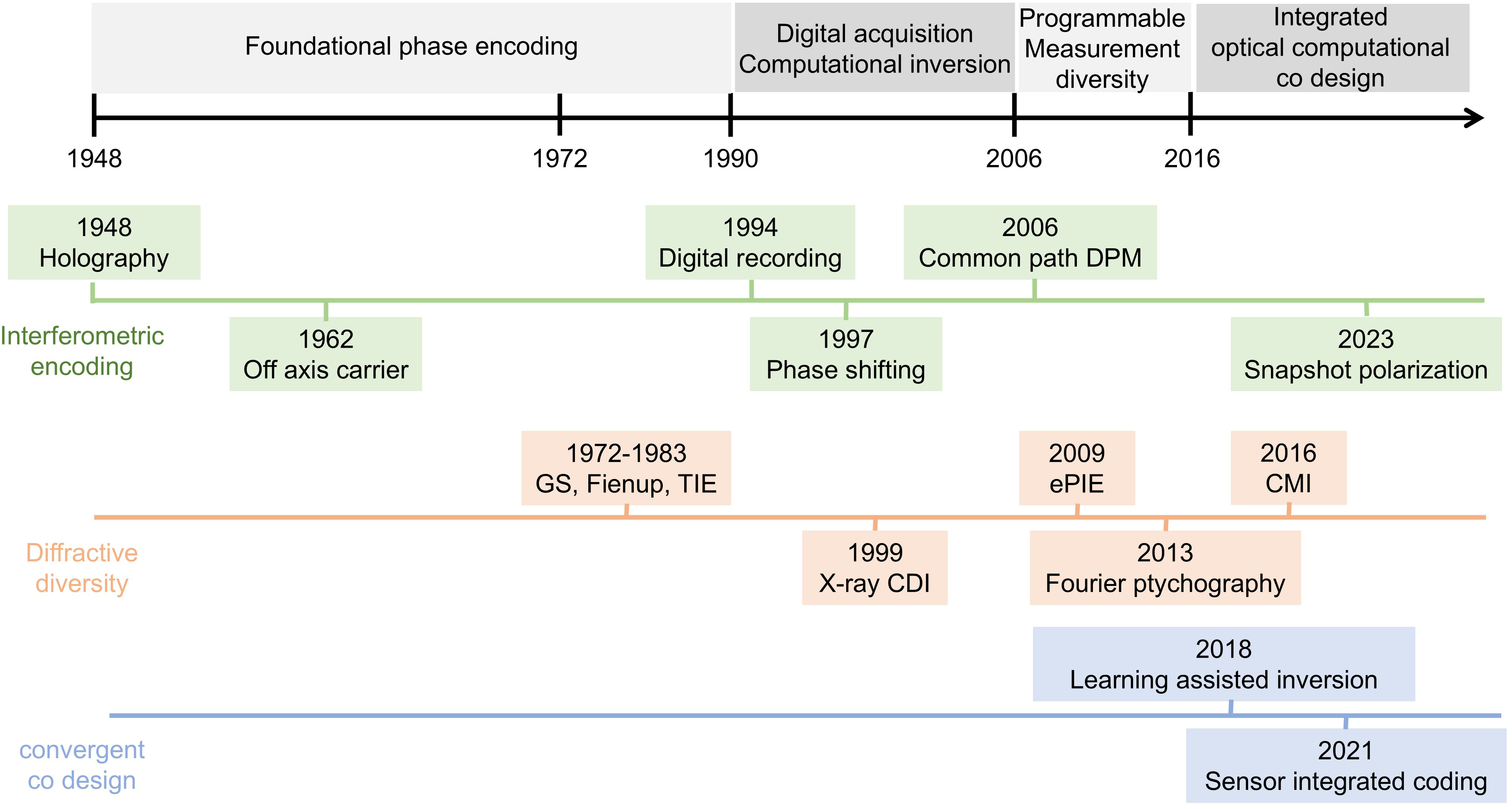
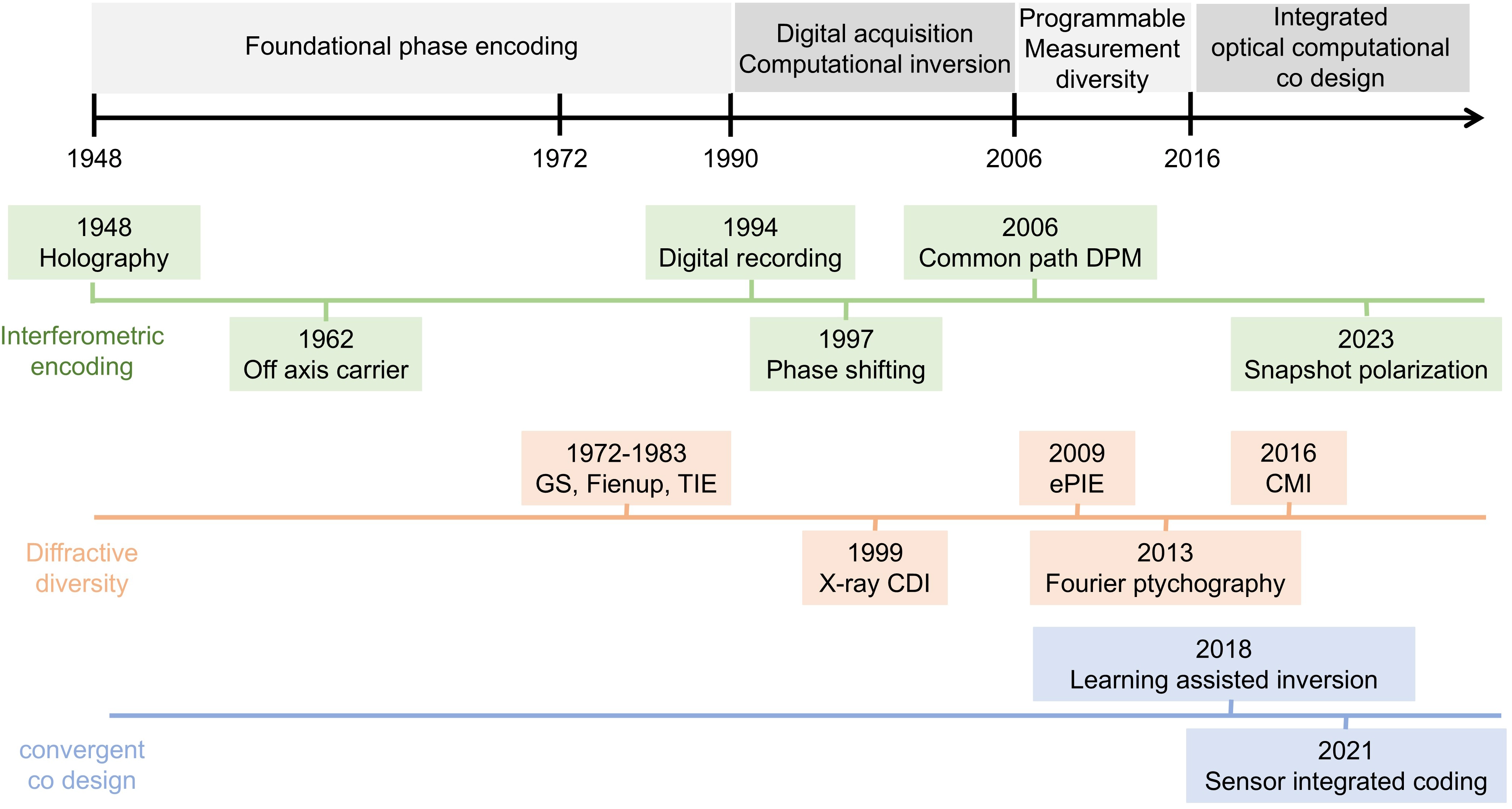
Figure 1. Selected milestones in the technical evolution of modulation-enabled phase imaging. The timeline highlights representative advances in interferometric phase measurement, diffractive phase retrieval, computational reconstruction, and optical-field modulation that shaped the framework of this review.GS: Gerchberg-Saxton; TIE: transport-of-intensity equation; CDI: coherent diffraction imaging; DPM: diffraction phase microscopy; CMI: coherent modulation imaging; ePIE: extended ptychographical iterative engine.
2. Theoretical Framework for Modulation-Enabled Phase Imaging
Before comparing individual modulation-based imaging schemes, it is useful to establish a common theoretical framework for how phase information is encoded into intensity measurements. Both interferometric and diffractive phase-imaging methods can be regarded as forward mappings from an object complex field to recorded intensity data, but they differ in how the missing phase becomes observable. Interferometric methods convert phase into object-reference interference terms, whereas diffractive methods infer phase from propagation- or diffraction-dependent intensity variations. This section first summarizes these two measurement principles, then formulates optical-field modulation as a forward-model design strategy, and finally introduces the diversity, identifiability, and trade-off criteria used to compare modulation strategies in the following sections.
2.1 Interferometric phase measurement and diffractive phase retrieval
Optical field can be represented as a complex-valued function:
In Equation (1), A(r) and φ(r) denote the amplitude and phase, respectively. Conventional image sensors directly record the intensity I(r) = |U(r)|2, whereas the phase must be converted into measurable intensity variations or inferred through a physical image-formation model. QPI primarily recovers phase-induced optical-path-length variations. Depending on the measurement configuration, some interferometric and diffractive methods additionally recover the field amplitude and therefore reconstruct the full complex optical field[1]. According to how phase information is encoded into intensity measurements, the methods considered in this review can be broadly divided into interferometric and diffractive approaches.
In interferometric measurements, the object field O(r) is superposed with a reference or self-reference field R(r). The recorded intensity can be written as:
In Equation (2), the superscript* denotes complex conjugation. The first two terms form the zero-order background, whereas the cross terms contain the relative phase between the object and reference fields. Interferometric phase measurement therefore requires the desired cross term to be separated from the background and conjugate term. Temporal phase shifting recovers the complex field by changing the reference phase over multiple exposures[20], whereas off-axis holography introduces a spatial carrier so that the interference terms can be separated in the spatial-frequency domain[21,22]. These principles underlie digital holographic and related quantitative phase microscopy methods[12,14].
Diffractive measurements recover the object field without introducing a separate reference arm. For object field O(r), the detector-plane field under the m-th measurement condition can be expressed as:
and the corresponding detector intensity is:
In Equations (3) and (4), Pm denotes the propagation or coherent imaging operator for the m-th measurement state and nm(r) represents measurement noise. Because the modulus-squared operation removes the detector-plane phase, a single intensity image is usually insufficient for stable complex-field recovery. Additional constraints may be introduced through support and oversampling in CDI[13,18], overlapping probe measurements in ptychography[17,61], or multiple defocus and propagation planes[16,28].
Interferometric and diffractive measurements therefore differ in how phase information becomes observable. Interferometric methods encode relative phase into object-reference cross terms and can support deterministic demodulation when the reference field and modulation states are sufficiently calibrated. Diffractive methods infer phase by solving a nonlinear inverse problem and depend more strongly on measurement diversity, object priors, and model accuracy. Nevertheless, both approaches can be described as mappings from an unknown object field to recorded intensity data. Optical-field modulation redesigns this mapping by controlling the illumination, reference field, propagation condition, or detection response.
2.2 Optical-field modulation as forward-model design
The essential role of optical-field modulation is to introduce controllable operators into the object-to-intensity mapping, thereby changing how phase information is encoded into measurable intensity data. In this sense, optical-field modulation is not merely the addition of an optical component, but a strategy for forward-model design.
For the m-th measurement state, a general modulated forward model can be written as:
where O(r) denotes the object complex field, L represents illumination-side modulation, P1,m and P2,m describe propagation or coherent imaging before and after a coding plane, C denotes detection-side or post-object coding, R (r) represents an explicit reference wave or an effective self-reference component, D (r) is the detector sampling and response operator, and n (r) denotes noise. For reference-free diffractive imaging, R (r) = 0. Operators that are absent in a specific system can be replaced by identity operators. Therefore, Equation (5) is not intended to reproduce every experimental configuration in full detail, but to provide a common notation for comparing how different modulation elements enter the object-to-intensity mapping.
Figure 2 maps illumination and propagation modulation, detection-side coding, detector response, and optional reference-field interference onto the imaging chain. Illumination-side modulation controls the incident field before it interacts with the object, for example through angular, spatial, spectral, polarization, or positional control. Reference-field modulation acts through R (r) and is mainly associated with interferometric systems, including phase shifting, off-axis carrier encoding, and common-path self-referencing[15,20,21]. Propagation modulation changes the field evolution between the object and detector, for example through defocus or multi-height acquisition[28]. Detection-side modulation uses coded apertures, phase masks, coherent modulators, diffusers, or sensor-integrated structures to encode the outgoing field before intensity detection[38,39].
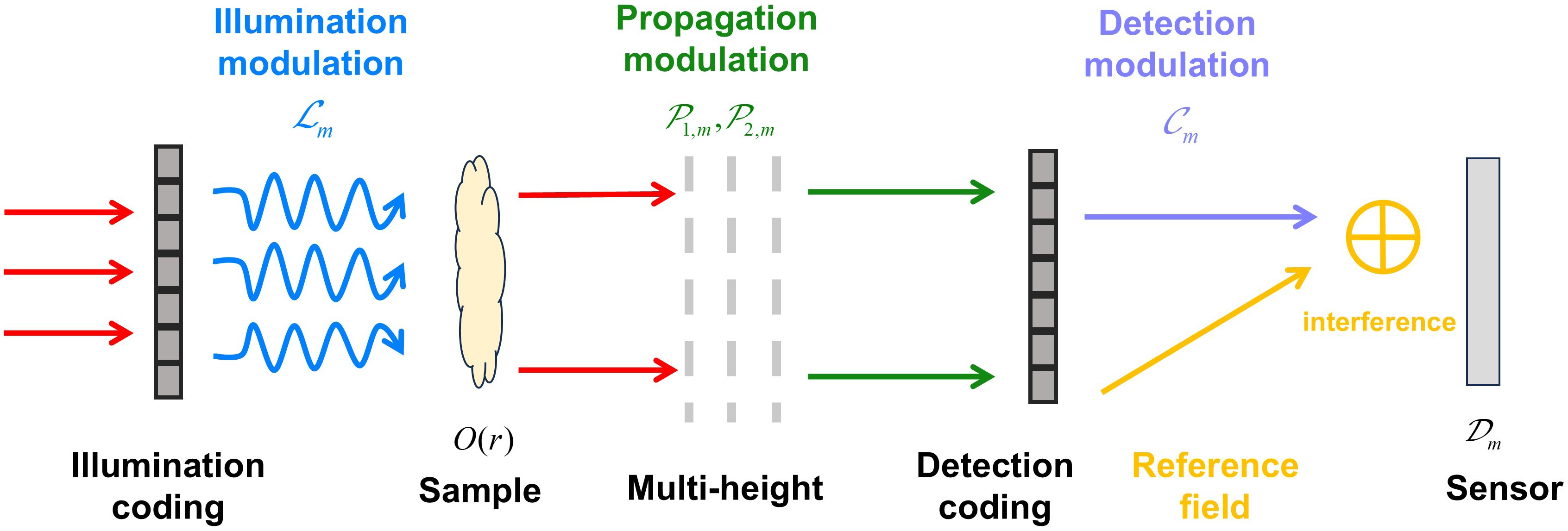
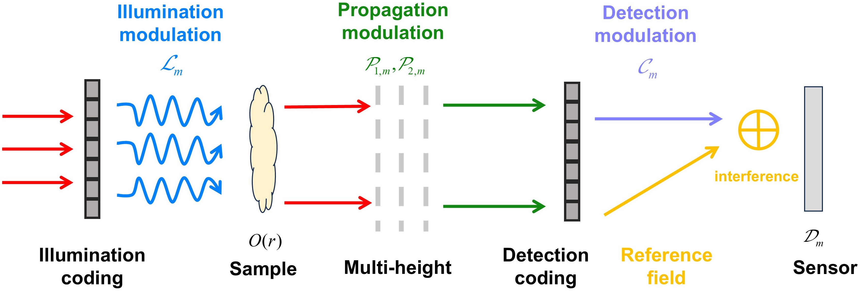
Figure 2. General forward-model representation of optical-field modulation.
To organize these strategies more systematically, this review classifies optical-field modulation along two complementary axes: the measurement mechanism and the modulation location. The first axis distinguishes interferometric measurement from diffractive intensity measurement. Interferometric systems use a reference or self-reference field to convert phase into measurable interference terms, whereas diffractive systems infer phase from intensity-only measurements through physical constraints and computational reconstruction. The second axis describes where the modulation is introduced, including the illumination side, reference field, propagation path, and detection side.
Table 1 summarizes this two-axis classification and lists representative examples for each combination of modulation location and measurement mechanism. By separating where modulation is introduced from how phase information is made measurable, the classification allows interferometric and diffractive systems to be compared within a common framework.
Table 1. Two-axis classification of optical-field modulation strategies.
| Modulation location | Interferometric measurement | Diffractive measurement |
| Illumination side | Angular or structured illumination in holographic phase imaging | Ptychography, coded illumination, Fourier ptychographic illumination |
| Reference field | Phase shifting, off-axis carrier encoding, common-path self-referencing | Usually absent; reference-free case with Rm (r) = 0 |
| Propagation path | Defocus or multi-plane interferometric measurements | Multi-height, defocus, or wavelength-dependent propagation diversity |
| Detection side | Detection coding with reference interference | Coded apertures, CMI, diffuser coding, sensor-integrated modulation |
CMI: coherent modulation imaging.
This classification provides the structural basis for comparing modulation strategies. The next section discusses how different forms of modulation diversity affect identifiability, robustness, acquisition speed, calibration burden, and other system-level trade-offs.
2.3 Modulation diversity, identifiability, and system trade-offs
Optical-field modulation can improve phase recovery when different measurement states impose complementary rather than merely repetitive constraints on the unknown object field. The source of this diversity depends on the controlled physical variable and may be spatial, angular, axial, spectral, polarization-dependent, or temporal. Building on the location-mechanism classification in Figure 2 and Table 1, this section examines how such diversity influences identifiability, robustness, acquisition speed, calibration burden, and other system-level trade-offs.
Here, identifiability refers to whether different object fields can be distinguished from the recorded intensity data under a given forward model. From an inverse-problem perspective, suitable modulation can improve identifiability by reducing nontrivial phase ambiguities, providing redundant object constraints, or expanding the spatial-frequency range transferred to the detector. For example, overlapping probe measurements provide real-space redundancy in ptychography[17,61], angular illumination expands frequency coverage in Fourier ptychography[19], and coded diffraction patterns can improve phase recoverability under appropriate sampling and object assumptions[36]. However, modulation does not automatically guarantee a unique or stable reconstruction. Its benefit depends on whether the resulting intensity responses are sufficiently independent, accurately modeled, and detectable under the available photon budget, detector sampling, and noise conditions[13,41].
Measurement diversity can be implemented either sequentially or through multiplexed acquisition. Sequential strategies, including temporal phase shifting, positional scanning, and multi-height recording, acquire different modulation states in separate exposures[20,28,61]. Because each state is individually recorded, these methods generally provide well-separated and relatively strong measurement constraints. Their principal limitations are increased acquisition time and sensitivity to sample motion, illumination fluctuation, and temporal system drift.
Multiplexed strategies instead encode several information channels within a single exposure using spatial carriers, polarization channels, static optical coding, or sensor-integrated modulation[21,38,39,59]. Such methods are more suitable for dynamic imaging, but different channels must share the available detector bandwidth and photon budget and may suffer from crosstalk or reduced sampling density.
The information gain provided by modulation must therefore be balanced against several practical costs. Increasing the number of modulation states generally strengthens reconstruction constraints but also increases acquisition and computational burdens. Strong amplitude modulation can generate distinguishable intensity responses but reduces optical throughput, whereas phase modulation usually preserves more photons while requiring accurate fabrication, wavelength-dependent calibration, and reliable knowledge of the modulation profile. Similarly, calibrated modulation reduces the number of unknown variables and improves reconstruction stability, while blind or self-calibrating reconstruction relaxes experimental calibration requirements at the expense of a more coupled inverse problem. Comparative studies of coded illumination have shown that reconstruction performance depends not only on the presence of modulation, but also on the coding pattern, modulation density, measurement number, optical efficiency, and consistency between the physical encoding and reconstruction model[41].
Consequently, there is no universally optimal modulation strategy. Snapshot and multiplexed approaches are preferable for rapidly varying samples, whereas high-resolution or low-noise imaging may tolerate sequential measurements to obtain stronger redundancy. Low-photon applications require modulation patterns with high optical throughput, while compact lensless systems may favor static detection-side or sensor-integrated coding. Practical system design should therefore jointly consider spatial resolution, FOV, signal-to-noise ratio, frame rate, photon efficiency, detector bandwidth, hardware complexity, calibration burden, dynamic adaptability, and reconstruction cost. These criteria provide the basis for comparing the interferometric and diffractive modulation strategies discussed in the following sections.
3. Optical-Field Modulation in Interferometric Phase Imaging
In interferometric phase imaging, object phase is encoded through interference between an object field and a reference or self-reference field. When the object-reference cross term can be isolated and the reference field is sufficiently known or calibrated, both the amplitude and phase of the object field can be recovered. Optical-field modulation improves this process by controlling the reference phase, spatial carrier, illumination state, propagation distance, polarization channel, or sampling pattern. These operations preserve the basic interference mechanism but determine how reliably the desired cross term can be separated from the zero-order background, conjugate image, coherent noise, and system drift.
To maintain consistency with the location-mechanism framework introduced in Section 2, this section organizes interferometric modulation according to the stage that is primarily controlled: reference-wave and interference encoding, illumination-state diversity, propagation-distance diversity, and coded detection and sampling. Some methods affect more than one stage; they are assigned according to their principal measurement function. Reconstruction and calibration are discussed separately because they influence all four routes. As summarized in Table 2, these strategies differ in measurement diversity, detector-bandwidth use, photon efficiency, calibration burden, and adaptability to dynamic samples.
Table 2. Comparison of representative interferometric modulation strategies for phase imaging.
| Modulation route | Implementations | Main benefit | Principal trade-off |
| Reference-wave phase control | Temporal and multiplexed phase shifting | Quantitative phase demodulation; snapshot operation is possible through multiplexing | Multi-frame motion sensitivity or channel-dependent calibration errors |
| Spatial-carrier and self-reference encoding | Off-axis holography, DPM, and programmable Fourier-plane filtering | Single-exposure reconstruction and improved interferometric stability | Detector-bandwidth consumption, Fourier-window selection, and reference contamination |
| Illumination-state diversity | Angular, structured, spectral, and random-field illumination | Speckle suppression, expanded frequency coverage, and multi-wavelength phase unwrapping | Usually requires multiple illumination states and source-dependent calibration |
| Propagation-distance diversity | Multi-plane and defocused interferometric measurements | Additional axial constraints without modifying the reference arm | Multi-frame acquisition and sensitivity to distance and sampling errors |
| Coded detection and sampling | Single-pixel and compressive holography | Compatibility with sensitive non-array detectors and compressed acquisition | Large pattern number, synchronization requirements, and prior-dependent reconstruction |
| Reconstruction and calibration | Model-based demodulation, constraint-assisted reconstruction, and learning-assisted correction | Compensation of residual errors and acceleration of inverse computation | Cannot recover unencoded information and remains vulnerable to model mismatch |
DPM: diffraction phase microscopy.
3.1 Reference-field modulation
Reference-wave control determines how the object-reference cross term is encoded and separated from the recorded interferogram. Temporal phase shifting changes the relative phase between the object and reference waves. Snapshot multiplexing records several phase-shifted channels simultaneously. Spatial-carrier encoding shifts the cross term in the Fourier domain, whereas common-path methods derive a reference from the sample-bearing field itself. These strategies share the same demodulation objective but distribute information differently across time, detector space, polarization channels, and spatial frequency.
3.1.1 Temporal phase-shifting modulation
Temporal phase-shifting modulation is the most direct route for quantitative interferometric phase recovery. By applying a known phase delay to the reference wave or undiffracted component, several intensity measurements are recorded under different modulation states and then demodulated to solve for the object phase. In Gabor-type in-line holography, a spatial light modulator (SLM) can modulate the low-frequency Fourier component to generate controlled phase shifts without an additional reference arm[65]. Reflective SLM configurations further simplify the optical path by assigning different regions of the modulator to object illumination and reference generation[66]. These designs make compact in-line complex-field reconstruction feasible, but their quantitative reliability depends on the independence and calibration of the phase-shifted measurements.
The accuracy of temporal phase shifting is governed by the conditioning of the modulation matrix. Three-step algorithms can recover phase when the phase steps are known, sufficiently separated, and the intensity background is stable. Four-step algorithms are widely used because quadrature phase steps simplify demodulation and partially balance intensity terms. More general least-squares or error-compensating phase-shifting algorithms become useful when the number of frames is larger than the minimum, when the phase steps are not exactly uniform, or when intensity fluctuations must be averaged across measurements[67,68].
The main experimental limitation is that the actual phase step rarely equals its nominal value exactly. Phase-step errors propagate into the reconstructed phase together with detector noise, source fluctuations, and reference-amplitude variations. Sample motion introduces an additional object-dependent error because phase-shifting algorithms assume that all frames correspond to the same object field. Temporal phase shifting can therefore provide high quantitative accuracy for static or slowly varying specimens but is less suitable for rapidly changing samples unless the phase states are multiplexed within one exposure. A representative two-arm implementation is shown in Figure 3, where a phase shifter in the reference arm introduces the prescribed temporal phase steps.
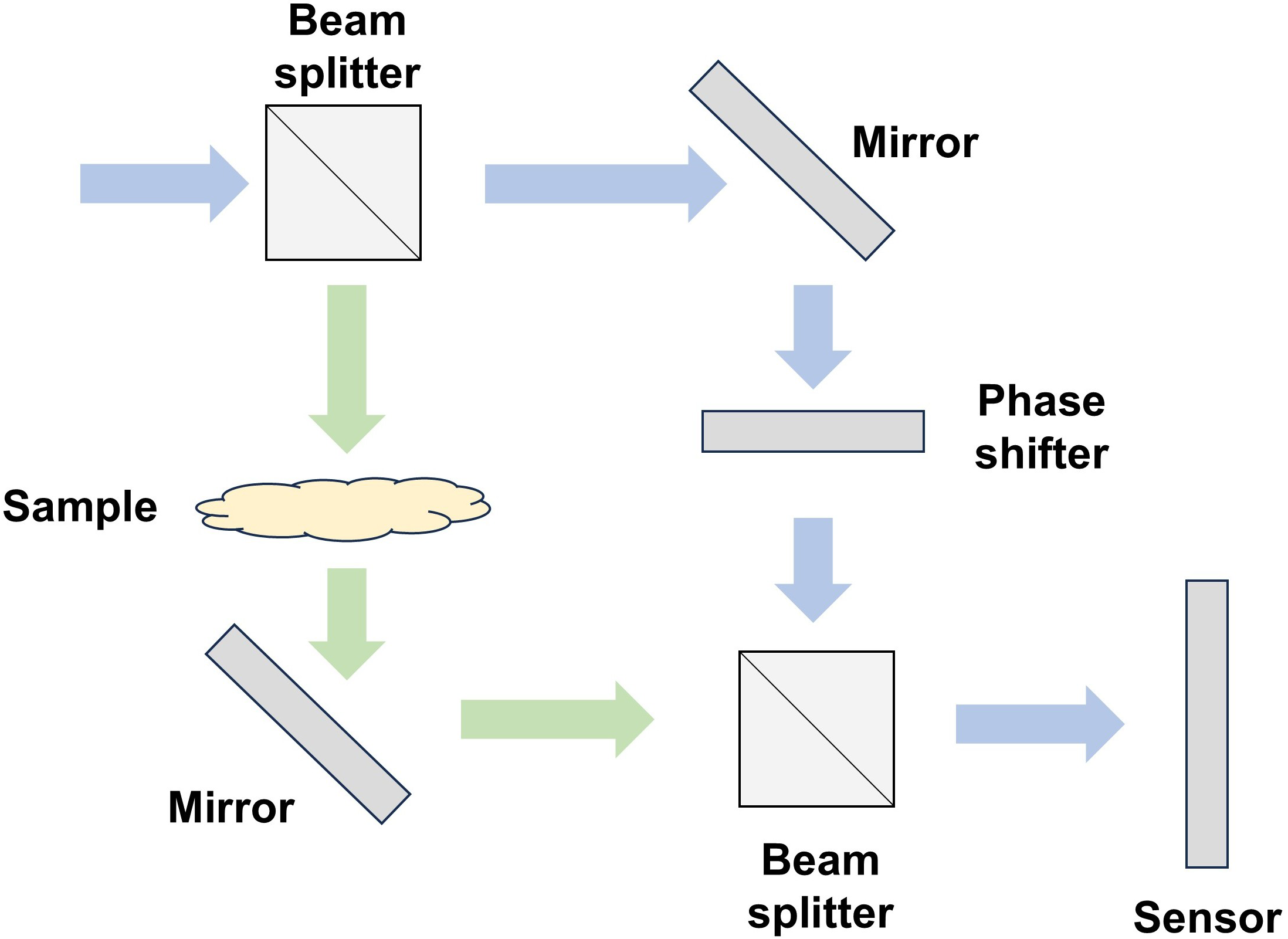
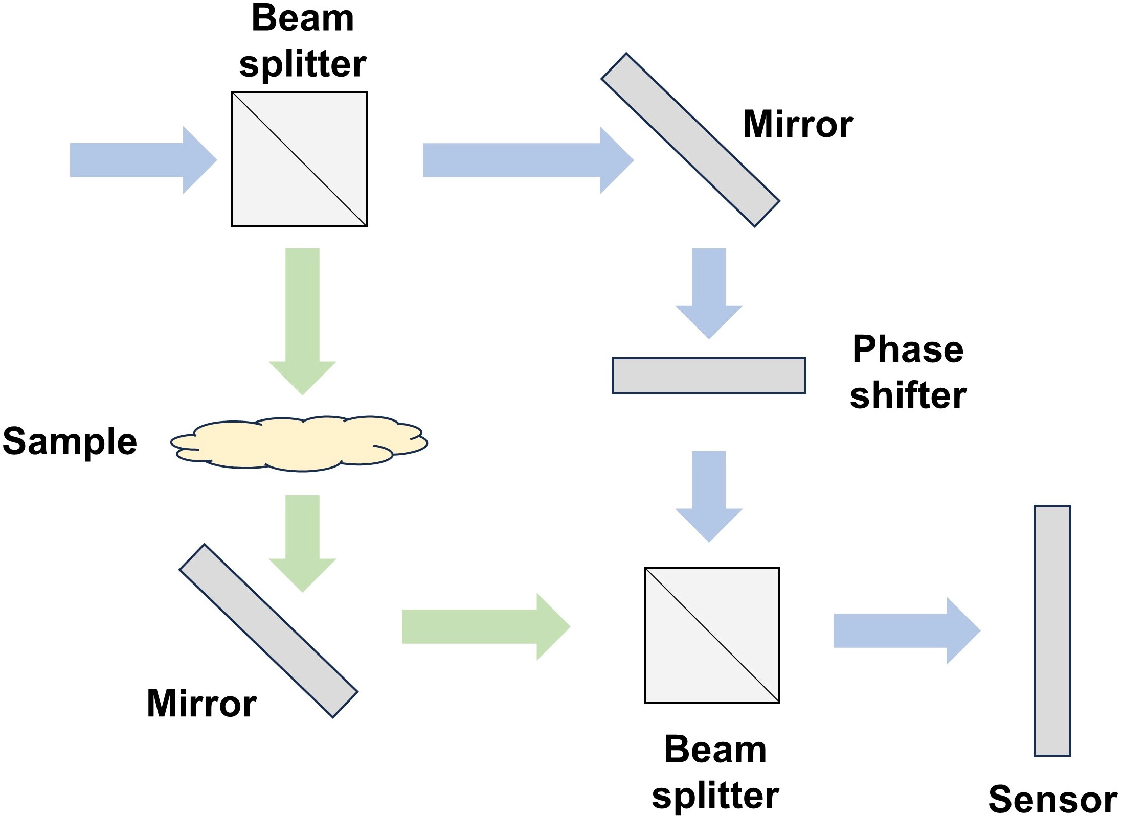
Figure 3. Schematic of temporal phase-shifting interferometry. A beam splitter separates the object and reference arms, and a phase shifter introduces known reference-phase steps before the beams are recombined at the sensor.
3.1.2 Snapshot multiplexed phase shifting
Snapshot multiplexed phase shifting replaces sequential acquisition with simultaneous recording of multiple phase-shifted interferograms. Space-division multiplexing encodes different phase-shifted holograms into different detector regions, enabling high-speed parallel phase-shifting digital holography[69]. Its main cost is that each phase-shifted channel receives only part of the detector area, which reduces effective sampling density and may introduce registration errors among sub-images. Polarization multiplexing provides a more compact route. Common-path Fizeau configurations combined with polarization cameras record multiple phase-shifted holograms in a single exposure, improving robustness against vibration and allowing dynamic complex-valued imaging[59]. Related single-path, incoherent, and grating-based methods further extend snapshot phase-shifting concepts to more light-efficient or less coherence-restricted configurations[70,71].
Figure 4 illustrates a representative polarization-camera implementation for parallel phase-shifting digital holography[60]. The object and reference beams are prepared with orthogonal polarizations, recombined, and passed through a quarter-wave plate before reaching a division-of-focal-plane polarization camera. The micro-polarizer array simultaneously records four polarization-resolved phase-shifted holograms, which are extracted and interpolated before four-step phase reconstruction. This design improves temporal resolution and suppresses zero-order and conjugate-image terms in a single exposure. However, snapshot polarization multiplexing introduces its own error sources: interpolation of micro-polarizer pixels can reduce spatial resolution, finite extinction ratio causes channel leakage, quarter-wave-plate retardance errors perturb the intended phase shifts, and pixel registration errors generate local phase artifacts. It is also important to distinguish this use of polarization from full vector-polarization imaging. In these systems, polarization mainly serves as a carrier for phase-shift multiplexing; it does not by itself recover the vectorial polarization state or full Jones-matrix or Mueller-matrix response of the sample. Therefore, this subsection only partially addresses vector polarization modulation, which requires a separate polarimetric forward model and additional measurements or constraints[49-52].
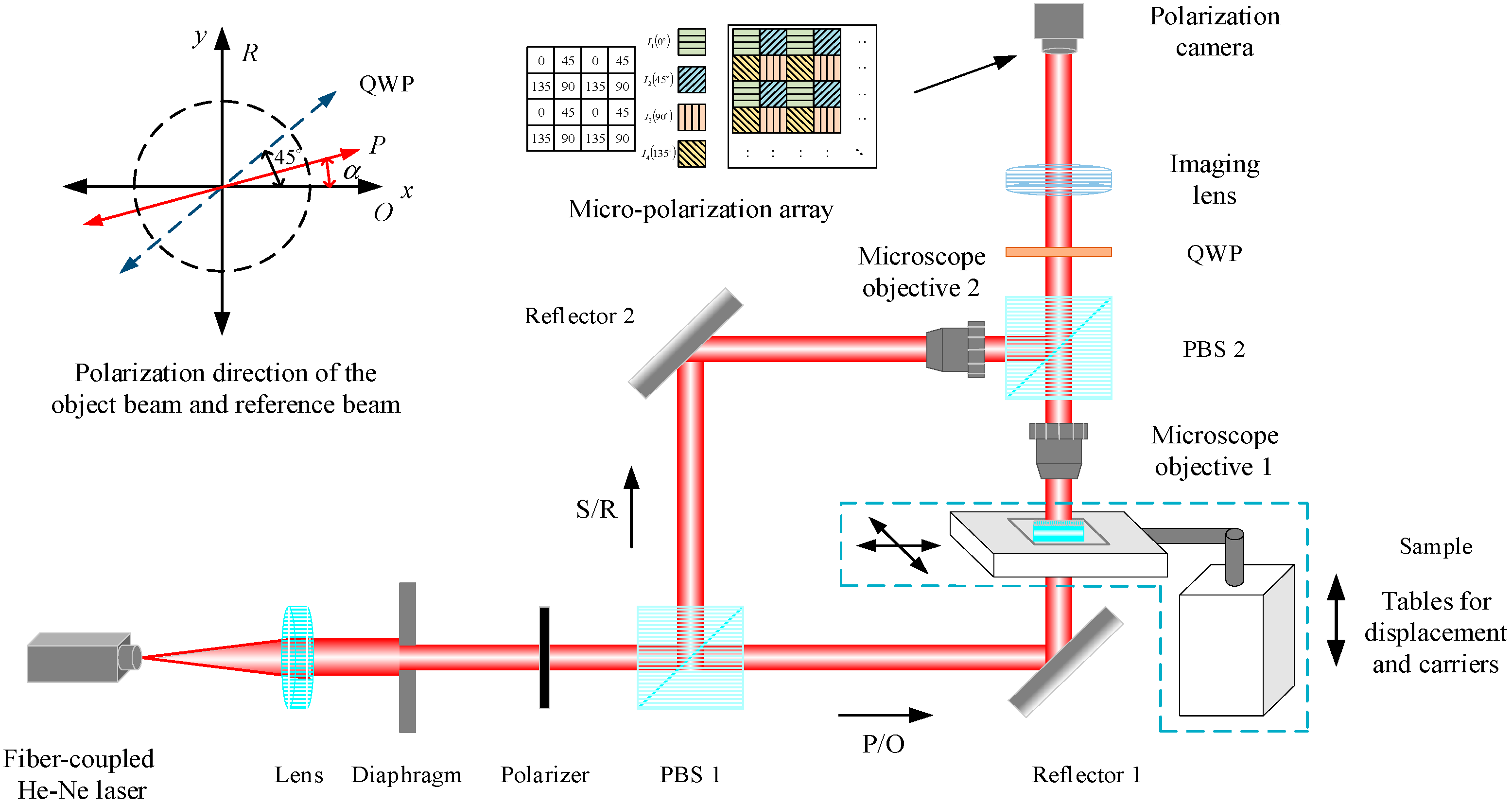
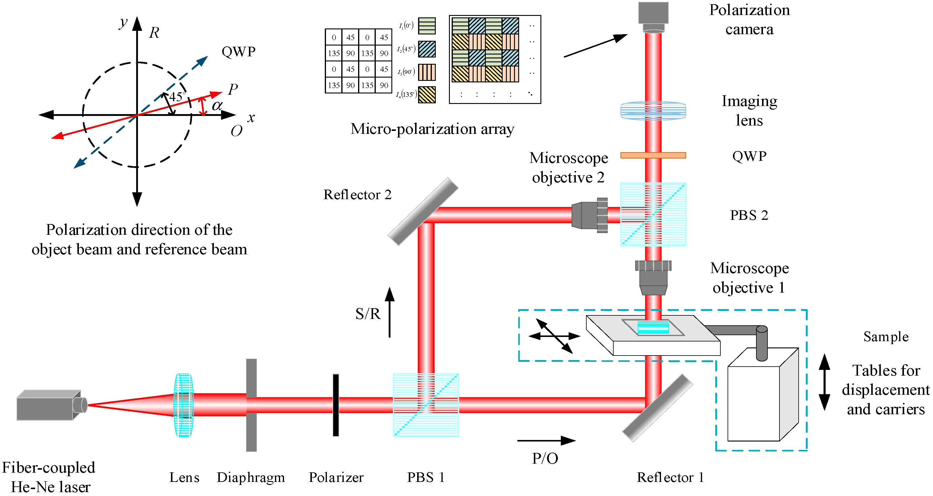
Figure 4. Snapshot polarization-multiplexed phase-shifting digital holography using a division-of-focal-plane polarization camera. Reproduced from reference[60]. CC BY 4.0. QWP: quarter-wave plate.
3.1.3 Spatial-carrier modulation
Spatial-carrier modulation separates the desired interference term in spatial-frequency space rather than through temporal phase stepping. In off-axis holography, the reference wave is tilted relative to the object wave, shifting the two conjugate cross terms away from the zero-order spectrum[21]. One first-order term is selected in the Fourier domain, shifted to the origin, and inverse transformed to recover the complex object field. This procedure is closely related to Fourier fringe analysis[72], and appropriate spatial-frequency filtering can suppress the zero-order background and conjugate image[22].
The principal advantage of spatial-carrier modulation is single-exposure complex-field reconstruction. Its main constraint is the finite spatial bandwidth of the detector. The carrier frequency must be sufficiently large to separate the cross term from the zero-order and conjugate terms, while the shifted object spectrum must remain within the detector Nyquist limit. A wider Fourier window preserves more object bandwidth but increases leakage from neighboring spectral terms. A narrower window improves spectral separation but removes high spatial frequencies and reduces spatial resolution.
Reference-wave curvature, non-telecentric imaging, optical aberrations, and imperfect alignment can also introduce phase ramps or slowly varying background errors. These terms must be calibrated or removed numerically. Off-axis holography should therefore be regarded as an exchange of temporal redundancy for detector-bandwidth allocation rather than simply as a faster version of phase-shifting interferometry. The corresponding off-axis configuration is schematically illustrated in Figure 5, in which the tilted reference beam introduces a spatial carrier at the sensor.
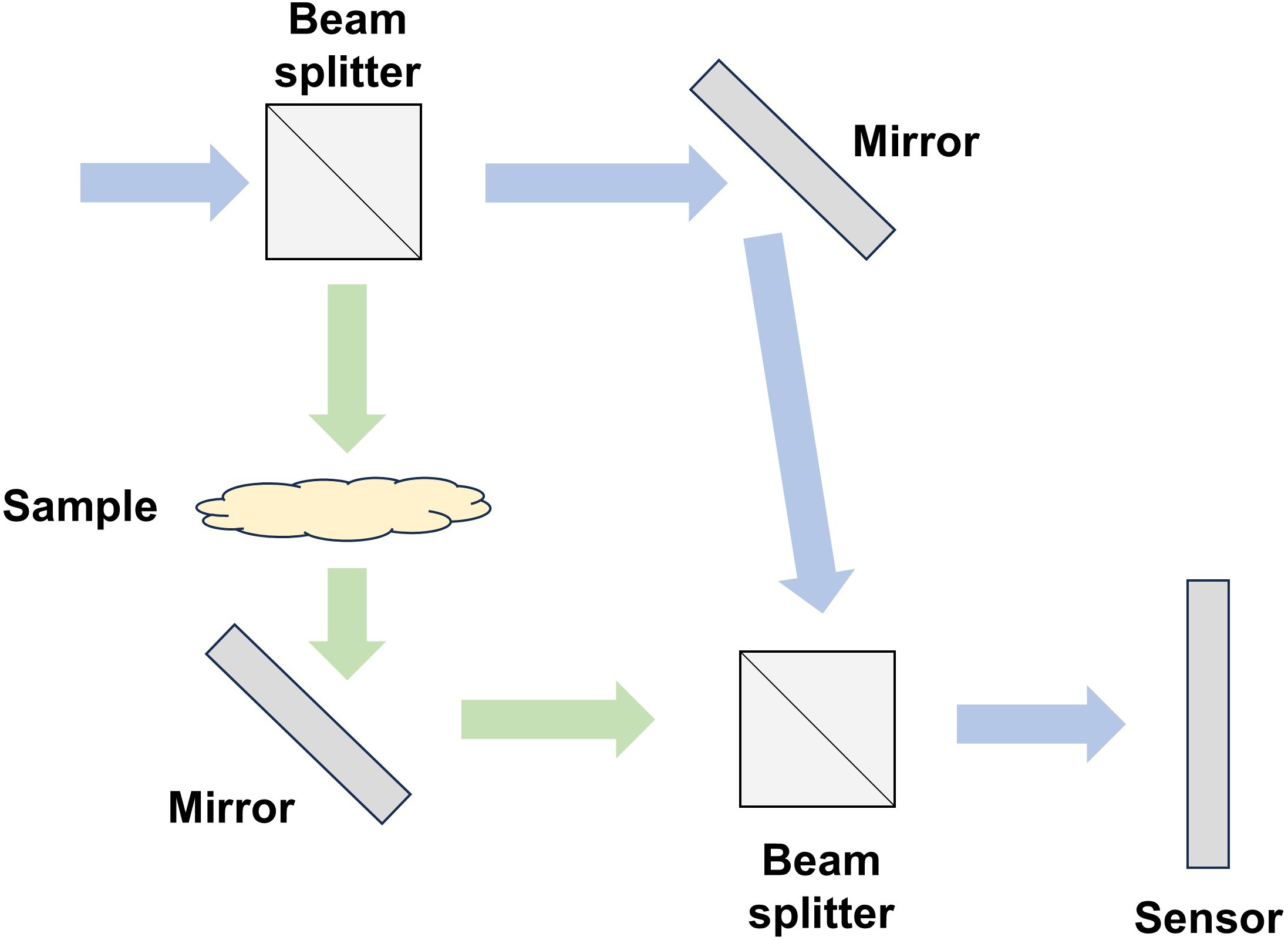
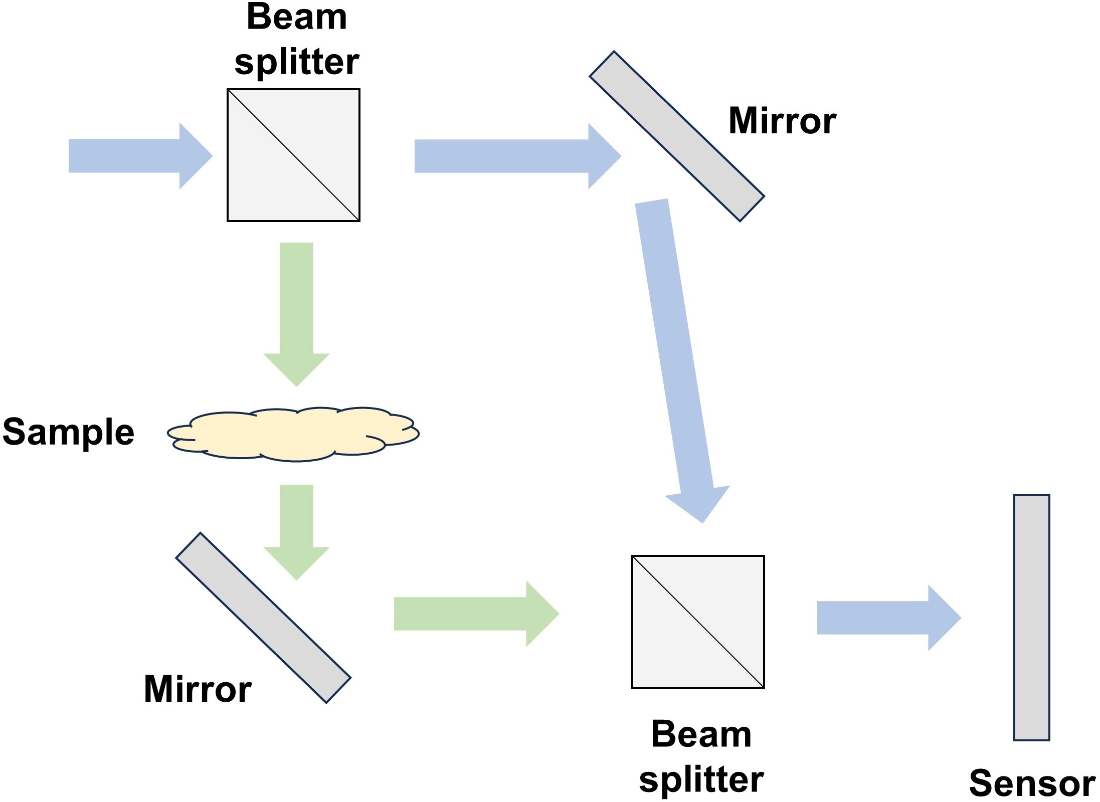
Figure 5. Schematic of off-axis spatial-carrier holography. The object and tilted reference waves interfere at the sensor, and their angular separation shifts the cross terms away from the zero-order spectrum.
3.1.4 Common-path self-reference generation
Common-path self-reference methods improve interferometric stability by deriving the reference wave from the same optical path as the object-bearing wave. DPM is a representative example. A phase grating splits the microscope image into diffraction orders; one order is low-pass filtered in the Fourier plane to form a smooth reference wave, while another order retains sample information as the imaging wave[15]. The recombination of these two orders generates an off-axis interferogram for quantitative phase recovery. Because the reference and object waves share most optical components, DPM reduces environmental sensitivity compared with separated arm interferometers while retaining single-shot operation.
The self-reference principle has been extended through multimodal and programmable implementations. Diffraction phase and fluorescence microscopy combines the DPM module with epi-fluorescence imaging, linking label-free phase information with molecular specificity[73]. White-light DPM suppresses coherent speckle by replacing laser illumination with spatially coherent white light while preserving the common-path geometry[74]. Compact holographic-camera designs use angular-selective diffraction in a thick holographic grating to generate the filtered reference beam and reduce alignment sensitivity[75]. More recently, programmable Fourier-plane phase masks have been used to tune the phase delay between background and structural spatial-frequency components for real-time label-free phase-contrast imaging[76].
The reliability of self-reference generation depends on whether the filtered field is sufficiently smooth and independent of the sample structure. An excessively small Fourier-plane aperture removes useful low-frequency object information, whereas an aperture that is too large allows sample features to contaminate the reference. Dense, strongly scattering, or spatially extended specimens can therefore introduce reference-dependent phase bias. Grating alignment, aperture placement, chromatic dispersion, and wavelength-dependent diffraction efficiency also affect quantitative accuracy. Figure 6 shows the common-path self-reference principle, in which a grating and Fourier-plane filtering separate the object-bearing and reference components before their recombination.
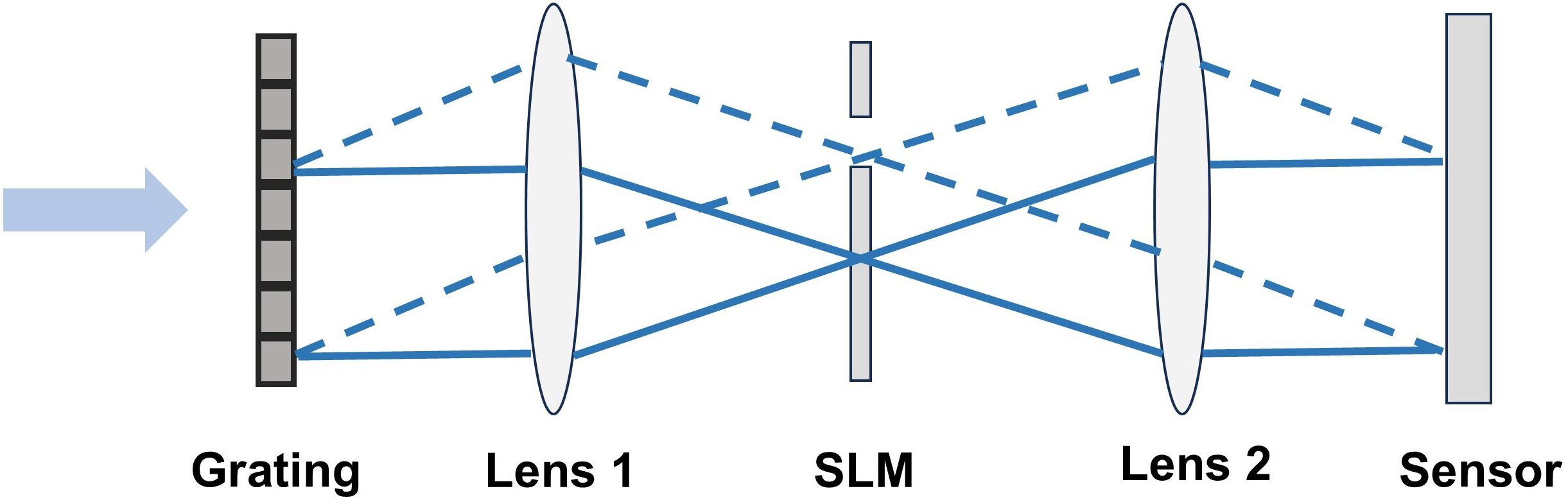
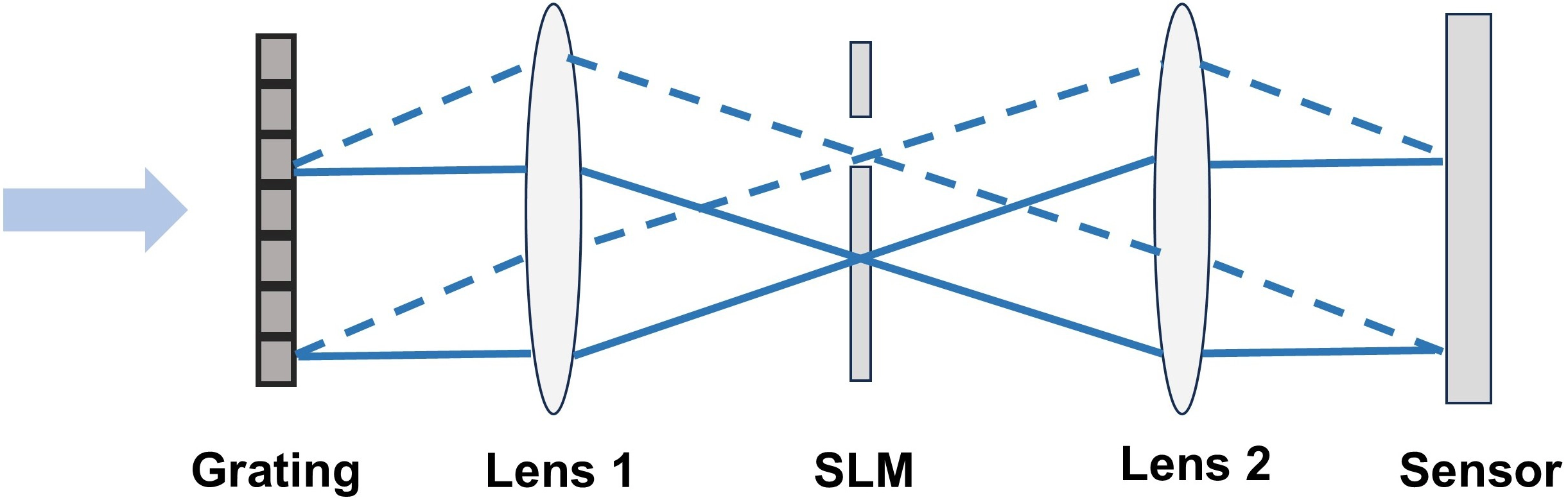
Figure 6. Schematic of common-path self-reference generation in DPM. A grating separates diffraction orders, and Fourier-plane filtering produces a smooth reference component that is recombined with the object-bearing component. DPM: diffraction phase microscopy; SLM: spatial light modulator.
3.2 Illumination-side modulation
Illumination-state diversity changes the object wave before interferometric demodulation by varying the incident angle, spatial structure, wavelength, spectral bandwidth, or random-field realization. These changes provide angular, spectral, or statistical diversity that can suppress speckle, expand spatial-frequency coverage, extend the phase-unwrapping range, or reduce twin-image artifacts. Because different illumination states are usually acquired sequentially, their information gain must be balanced against acquisition time and sample motion.
3.2.1 Angular and structured illumination
Angular illumination modulation changes the incident wavevector and thereby changes the object spatial frequencies transferred through the imaging system. In digital holography, a phase-only SLM can generate tilted illumination beams whose speckle patterns are partially decorrelated; averaging multiple holograms then reduces coherent speckle noise without mechanical scanning[77]. In reflection-mode holography, multidirectional illumination generated by the liquid-crystal-on-silicon spatial light modulator (LCoS-SLM) can access surface regions that are not measurable under normal incidence, extending the measurable gradient range of reflective microstructures[78]. These methods mainly provide statistical redundancy and angular coverage, but they generally require multiple exposures.
Structured illumination can also be introduced into common-path or lensless digital holographic configurations. As shown in Figure 7, in a recent structured-illumination lensless digital holographic microscope, an SLM sequentially generates fringe patterns with multiple orientations and phase shifts[79]. Spatial filtering retains the ±1 diffraction orders, producing two laterally sheared copies of the object wave that interfere at the detector. The reconstructed waves are digitally refocused along the corresponding illumination directions and averaged across orientations, thereby suppressing the defocused twin-image contribution and extending the effective recording bandwidth.
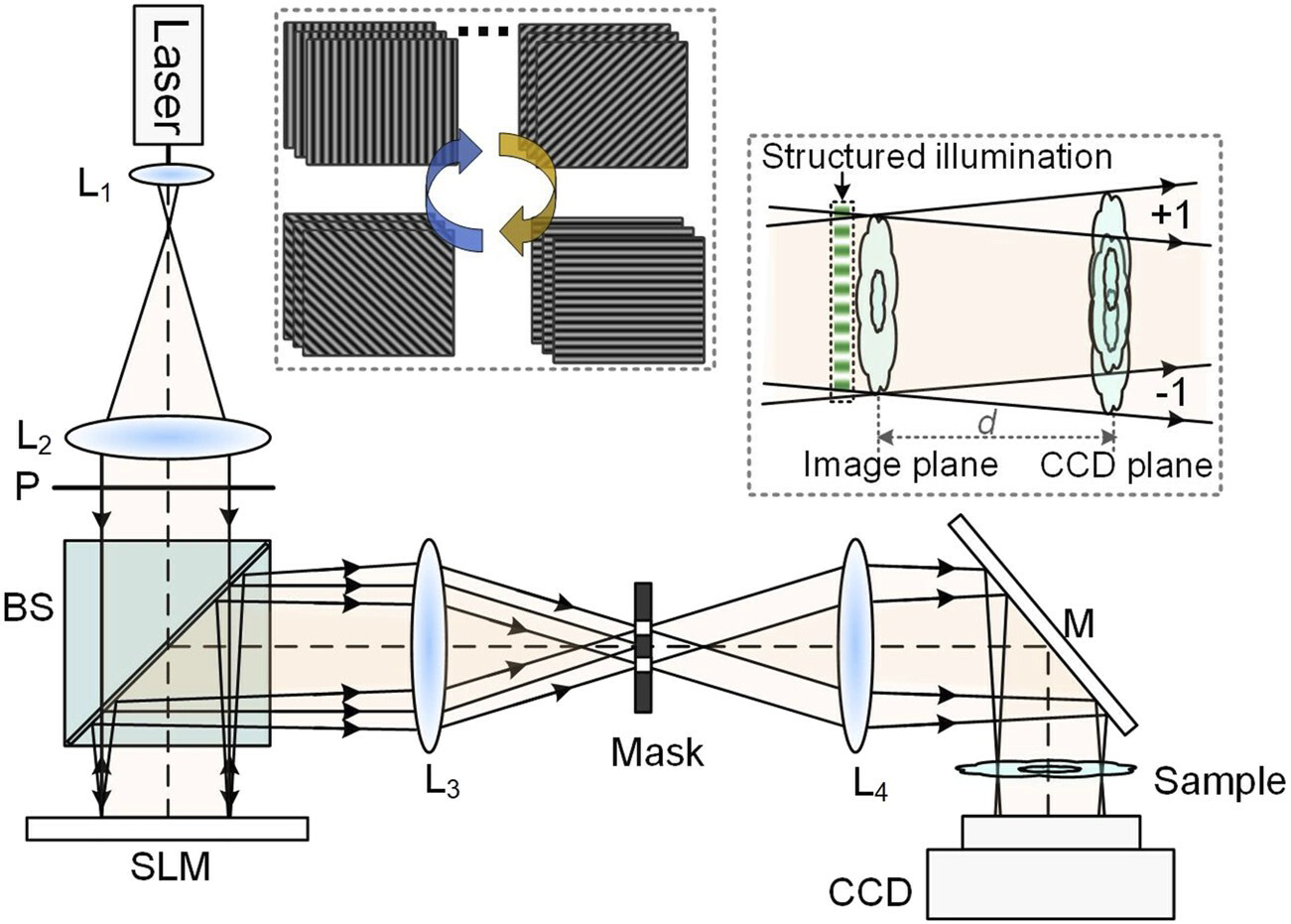
Figure 7. Schematic of structured-illumination lensless digital holographic microscopy. Reproduced from reference[79]. CC BY 4.0. BS: beam splitter; SLM: spatial light modulator; CCD: charge-coupled device.
In the reported implementation, eight illumination orientations and three phase shifts per orientation were used, requiring 24 sequential interferograms for one phase reconstruction. The method therefore improves reconstruction quality and spatial-frequency coverage, but its multi-state acquisition remains unsuitable for rapidly varying or nonrepeatable specimens unless the illumination states are further multiplexed or reduced.
3.2.2 Spectral tuning and coherence-length control
Spectral tuning changes the central wavelength and bandwidth of the illumination source. Because temporal coherence length is determined by the source spectrum, bandwidth adjustment also changes the optical-path-difference range over which high-visibility interference can be recorded. This relationship is more accurately described as spectral tuning with coherence-length control than as a general form of coherence modulation.
In digital holographic microscopy, SLM-based pulse shaping can tune both the source bandwidth and central wavelength[80]. Bandwidth tuning allows the coherence length to be adapted to the optical-path difference of the interferometric geometry. A broader spectrum can suppress coherent speckle, but excessive bandwidth reduces fringe visibility when the object-reference path difference exceeds the coherence length.
Central-wavelength tuning supports multi-wavelength phase reconstruction. Measurements at two or more wavelengths can be combined to form a synthetic wavelength, extending the unambiguous optical-path-difference range for high-aspect-ratio structures. The achievable range and noise sensitivity depend on the wavelength separation and the accuracy of the individual phase measurements. Multi-wavelength recovery also requires wavelength-dependent calibration of magnification, aberrations, phase shifts, diffraction efficiency, and system dispersion. Spectral tuning therefore provides a useful route to phase-range extension and speckle control, but it introduces calibration requirements that are absent from single-wavelength reconstruction.
3.2.3 Random and speckle modulation
Random or speckle modulation should be separated into statistical decorrelation and deterministic coding. Diffuse illumination can reduce twin-image artifacts because the desired object information remains correlated whereas the conjugate image varies across random realizations[81]. This statistical route improves robustness by averaging or suppressing unstable artifacts, but it typically requires multiple random states. In contrast, diffuser-based in-line holography incorporates a known random modulation into the reconstruction model, preserving compact geometry while reducing twin-image contamination[82]. Randomness-assisted in-line holography further combines speckle-modulated intensity patterns with correlation-based hologram formation and learning-assisted reconstruction[83]. These methods can improve noise robustness and high-frequency recovery, but their performance depends on random diversity, calibration of the modulating element, and consistency between the physical forward model and the reconstruction algorithm.
Designed-periphery and digital-periphery methods are related but should not be grouped as random phase modulation. They are better interpreted as constraint-assisted reconstruction: a designed periphery supplies a known boundary or support-like constraint for single-shot complex-object recovery[84], whereas a digital periphery extracts boundary information from a preliminary reconstruction and uses it as an iterative constraint[85]. A representative randomness-assisted in-line holographic setup is shown in Figure 8, where a SLM and a rotating ground glass generate random illumination states before complementary metal-oxide-semiconductor (CMOS) detection.
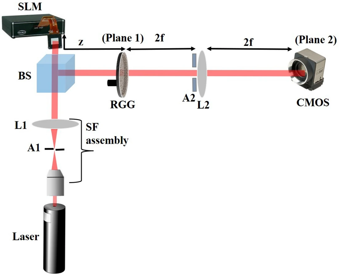
Figure 8. Experimental configuration for randomness-assisted in-line holography. The RGG generates statistically varying speckle fields, while the SLM defines the test object and the CMOS camera records the propagated random intensity patterns. Reproduced from reference[83]. CC BY 4.0. BS: beam splitter; RGG: rotating ground glass; SLM: spatial light modulator; CMOS: complementary metal-oxide-semiconductor; SF: spatial filter.
3.3 Propagation-distance diversity
Propagation-distance diversity changes the transfer operator between the object and detector without modifying the reference arm or illumination state. Recording interferograms at different axial planes produces wavefronts that have undergone different amounts of free-space propagation. The resulting measurements provide complementary constraints on the complex object field.
Multi-plane interferometric methods reconstruct the complex wavefront from a sequence of interferograms recorded at different axial planes[86,87]. In these systems, each measurement retains object-reference interference, while the change in propagation distance provides complementary constraints on the object wavefront. Related axial-diversity methods, including transport-of-intensity and multi-plane intensity-based phase retrieval, exploit the same propagation-induced redistribution of phase information without requiring an explicit reference field[88-91].
The principal limitation is the need to acquire several axial states. Multi-plane recording increases acquisition time and introduces sensitivity to sample motion, illumination drift, propagation-distance error, wavelength uncertainty, and changes in detector sampling between planes. Axial diversity is consequently most useful for static or repeatable specimens unless the planes can be recorded simultaneously or encoded within one exposure. Figure 9 schematically illustrates this axial-diversity acquisition, in which the same object wave is recorded at several calibrated sensor distances.
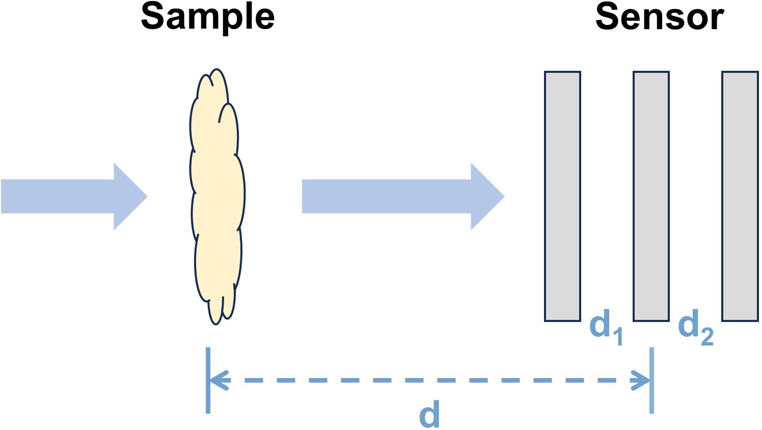
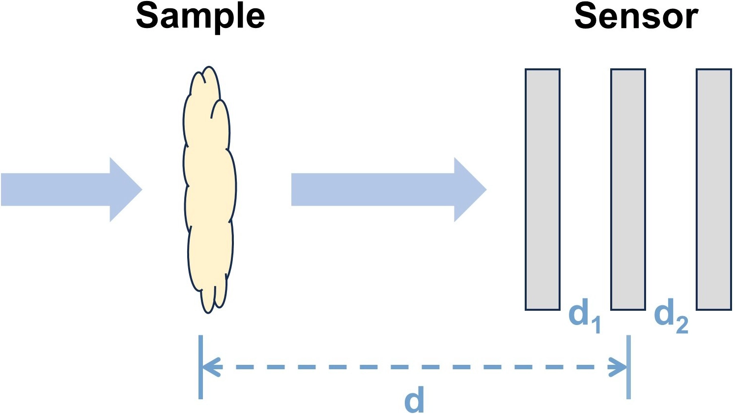
Figure 9. Schematic of propagation-distance diversity. The same sample field is recorded at multiple calibrated axial sensor positions, providing complementary propagation constraints.
3.4 Coded detection and single-pixel sampling
Coded detection changes how the interferometric signal is sampled rather than how the interference term is formed. Although the coding patterns may be introduced in the illumination, object, or reference arm, single-pixel methods are grouped here because their defining operation is the recovery of spatial information from sequentially coded, spatially integrated measurements. This distinction prevents the physical location of an SLM or digital micromirror device (DMD) from being confused with the measurement role of the coding process.
In single-pixel holography, spatial information is encoded by a sequence of SLM or DMD patterns, while a non-imaging detector records the integrated interferometric response. Phase shifting, heterodyne detection, or related demodulation methods recover the complex coefficient associated with each pattern. Compressive single-pixel holography has demonstrated complex-field reconstruction using Hadamard-pattern sampling and phase-shifting interferometry[92]. Phase-encoded illumination subsequently increased implementation flexibility by allowing the coding operation to be introduced in either the object or reference channel[93].
The measurement burden depends on whether the coding basis is fully sampled or compressed. Full Hadamard sampling requires a number of measurements comparable to the number of reconstructed pixels, whereas compressive sampling reduces the number of measurements by assuming sparsity or other priors. Replacing liquid-crystal SLMs with DMDs increases the pattern refresh rate, but the DMD refresh rate is not identical to the final complex-field frame rate because each reconstructed frame may require many patterns and phase-demodulation states[94]. Compact single-pixel schemes improve stability by using binary phase masks for Hadamard encoding and an unmodulated mask region as the reference field[95].
High-throughput single-pixel compressive holography further improved coding efficiency by combining binary-amplitude Hadamard-like illumination with heterodyne phase stepping[96]. As shown in Figure 10, this design directly projects binary-amplitude patterns onto the sample and uses a beat frequency between signal and reference beams to generate temporal phase stepping. It achieved a space-bandwidth-time product (SBP-T) of 41,667 pixels/s and complex-field reconstruction up to 256 × 256 pixels[96]. This result is valuable because it reports an explicit throughput metric rather than only a modulation speed. However, the practical frame rate still depends on pattern number, detector bandwidth, synchronization accuracy, signal-to-noise ratio, and reconstruction assumptions.
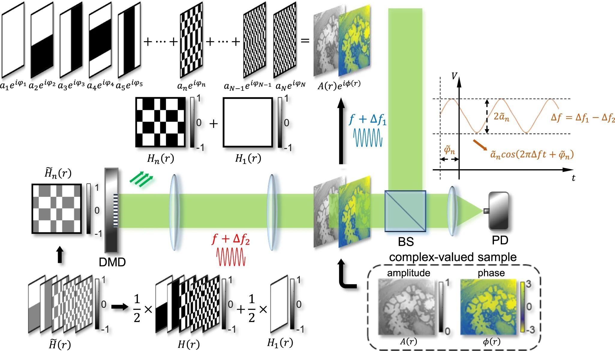
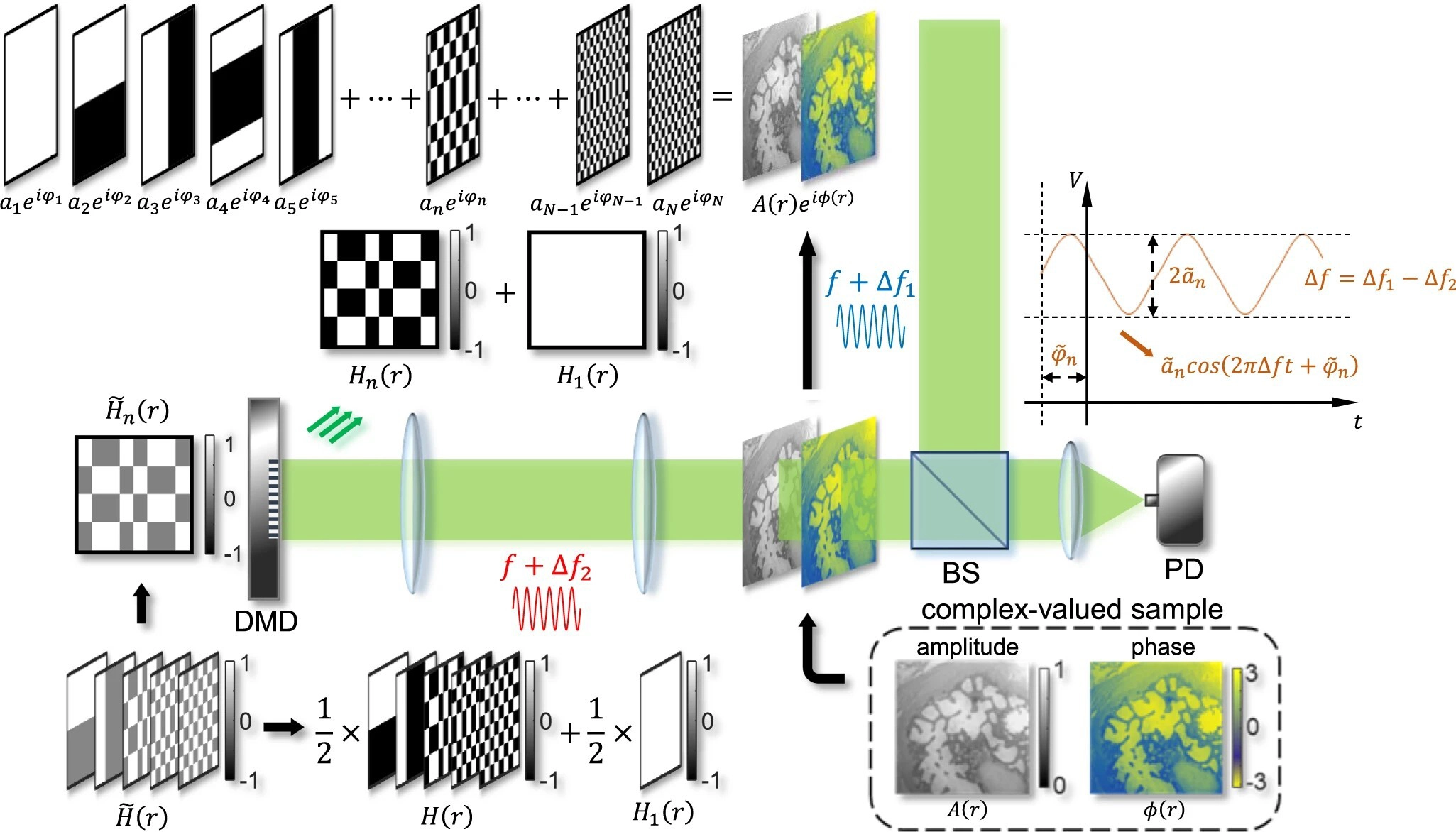
Figure 10. Principle of high-throughput single-pixel compressive holography. Reproduced from reference[96]. CC BY 4.0. BS: beam splitter; DMD: digital micromirror device; PD: photodetector.
Single-pixel interferometric coding is particularly attractive when pixelated detector arrays are expensive, noisy, slow, or unavailable. This is why single-pixel and compressive imaging concepts have been influential in terahertz imaging, where detector-array technology is more constrained than in visible-light microscopy[54,97,98]. Single-pixel architectures may also benefit low-light imaging because a single sensitive detector can collect more photons per measurement than a small pixel in an array detector, although low-photon operation imposes strict requirements on photon-efficient modulation and noise-aware reconstruction[99]. For ordinary visible-light high-speed microscopy, however, single-pixel holography is not automatically superior to camera-based holography because sequential pattern projection can become the limiting factor[100].
3.5 Reconstruction, calibration, and model mismatch
Reconstruction in modulated interferometric imaging should be treated as model-based demodulation under calibration constraints. The role of the algorithm is not only to invert an ideal forward model, but also to tolerate phase-step errors, reference-wave aberrations, channel-gain imbalance, detector noise, and imperfect knowledge of the modulation device. This perspective is more useful than listing reconstruction formulas, because the dominant failure mode in practical systems is often model mismatch rather than the absence of a nominal inverse algorithm.
For temporal phase shifting, the m-th interferogram can be written in a compact form as:
Here, I (r) is the m-th recorded interferogram, A is the slowly varying background intensity, B(r) is the fringe modulation amplitude, φ(r) is the object phase to be estimated, δ is the nominal phase shift, ε is the phase-shift error, n is measurement noise. This model assumes that the object field does not change during the M exposures. Three-step and four-step algorithms solve Equation (6) under fixed phase-step assumptions, whereas least-squares or error-compensating algorithms use additional frames or relaxed phase-step constraints to reduce sensitivity to ε and intensity fluctuation[20,67,68]. However, increasing M also increases acquisition time, so the same redundancy that improves numerical conditioning can reduce dynamic adaptability.
For off-axis holography, reconstruction relies on spectral separation of the zero-order term and the two conjugate cross terms. A simplified Fourier-domain representation is:
where F is the Fourier transform of the recorded interferogram, u is the spatial-frequency coordinate, C0 is the zero-order spectrum, C+ and C- are the two conjugate first-order spectra, and u is the carrier frequency introduced by the tilted reference wave. The object field is recovered by windowing one first-order term, shifting it to the origin, and applying an inverse Fourier transform[22,72]. Equation (7) is valid only when the carrier frequency is large enough to separate the spectra and small enough that the selected object bandwidth remains within the detector Nyquist limit. A narrow Fourier window suppresses crosstalk but removes high spatial frequencies, whereas a wide window preserves resolution but increases leakage from neighboring spectral terms. Reference-wave curvature, non-telecentric imaging, and aberrations further introduce background phase terms that must be calibrated or subtracted.
For coded or single-pixel interferometric measurements, phase-demodulated samples can be expressed as a coded linear inverse problem:
In Equation (8), x is the vectorized complex field or phase-related unknown to be reconstructed, y is the vector of coded measurements, A is the measurement matrix determined by Hadamard patterns, DMD masks, diffuser states, or other modulation operators, and η represents measurement noise and synchronization error. If A is square and well conditioned, full-basis reconstruction can be performed by direct inversion. By contrast, when measurements are fewer than unknowns, the inverse problem is underdetermined and requires compressive reconstruction based on sparsity, smoothness, learned priors, or object-domain constraints[92-96]. Designed-periphery and digital-periphery methods fit this broader logic because they provide additional support-like constraints when the measured hologram alone is insufficient[84,85]. The reliability of Equation (8) depends on whether the actual projected patterns, detector timing, illumination stability, and sample structure match the assumed model.
Learning-assisted reconstruction should therefore be classified by the role of the network in the inverse problem. Supervised end-to-end networks can provide fast inference after training, but they require paired data and may fail when the sample type, noise level, or optical configuration differs from the training distribution[101,102]. Physics-constrained or self-supervised methods reduce the need for ground-truth phase labels by embedding the holographic forward model into the loss, but they often require sample-specific optimization and remain sensitive to calibration errors[103]. Untrained deep-prior methods avoid external training datasets, but they are computationally slower and may fit noise or twin-image artifacts if regularization is weak. Hybrid approaches are often more defensible for quantitative imaging because the network is used for denoising, aberration compensation, phase-step correction, or twin-image suppression while the physical demodulation model remains explicit.
The key boundary is that reconstruction cannot recover phase information or spatial frequencies that were never encoded by the optical measurement. Neural networks can introduce priors, accelerate inverse computation, and compensate residual model errors, but they do not replace modulation design. In out-of-distribution samples, learning-assisted reconstructions may introduce plausible but incorrect structures. Future interferometric modulation should therefore integrate optical coding, calibration, uncertainty estimation, and physics-informed reconstruction, rather than treating deep learning as a universal substitute for physically informative measurements[43,101-103].
4. Optical-Field Modulation in Diffractive Phase Imaging
Diffractive phase imaging estimates object phase, and, where supported, field amplitude, from intensity distributions recorded after coherent or partially coherent propagation. Unlike interferometric methods, it does not require a separately generated reference beam, which is advantageous for compact, lensless, and short-wavelength systems. The absence of an explicit reference, however, also means that the detector-plane phase is removed by the modulus-squared measurement. A single unmodulated intensity image is therefore generally insufficient for stable recovery unless strong support, sparsity, or object-domain assumptions are available[13,18].
Optical-field modulation addresses this limitation by deliberately changing the object-to-intensity mapping so that multiple measurements, or a carefully encoded single measurement, contain complementary constraints on the same unknown field.
For the m-th measurement state, a general diffractive forward model may be expressed as
In Equation (9), O is the object complex field; L denotes illumination-side modulation; P1,m and P2,m are propagation or coherent-imaging operators; C represents post-object coding, such as an aperture, phase mask, diffuser, or sensor-integrated structure; D describes detector sampling and response; and n is measurement noise. Modulation may therefore act through the incident field, the propagation condition, or the detection path. These locations are physically distinct, but they share the same objective: increasing the independence and conditioning of the intensity constraints while controlling acquisition time, photon loss, calibration burden, and computational complexity.
As shown in Figure 11, the physical modulation routes considered here are illumination-side modulation, propagation diversity, and detection-side or sensor-integrated modulation. Illumination-side modulation changes how the specimen is interrogated; propagation diversity changes how the same exit wave evolves before detection; and detection-side modulation encodes the post-object field before intensity sampling. Reconstruction and calibration are treated separately because they affect all three physical routes. Table 3 compares their measurement formats, representative parameters, primary advantages, and dominant limitations.
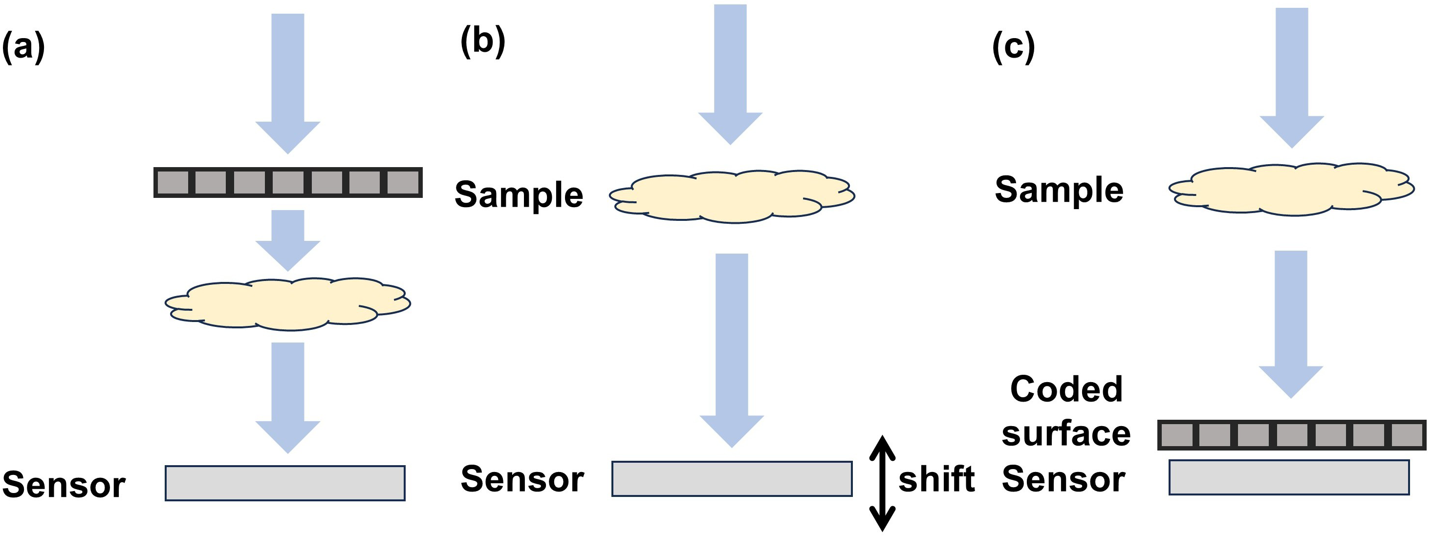
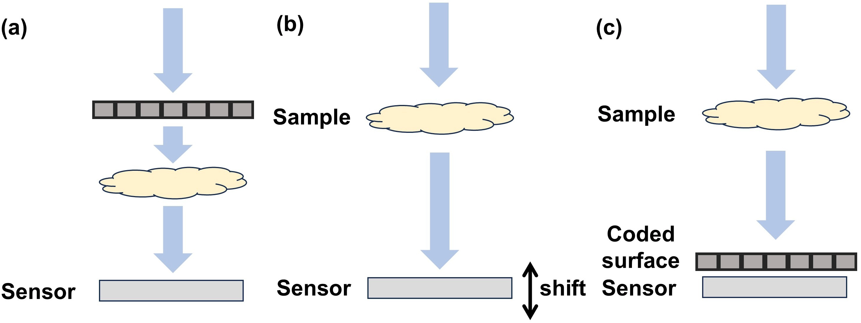
Figure 11. Representative comparison of modulation routes for diffractive phase imaging. (a) Illumination-side modulation changes the incident field before it reaches the sample, for example through coded masks, structured probes, diffusers, or angular illumination; (b) Propagation or axial diversity records the same exit wave at different propagation distances or sensor positions, allowing phase information to be inferred from intensity evolution; (c) Detection-side coding modulates the post-sample wavefield with an aperture, phase mask, diffuser, coded surface, or sensor-integrated structure before detection.
Table 3. Representative comparison of modulation routes for diffractive phase imaging.
| Route | Measurement format | Representative parameter | Primary advantage | Dominant limitation |
| Random-mask coded CDI | One diffraction pattern per mask; full-field modulation | Three binary patterns were used in reduced-modulation CDI[104]; a separate DMD implementation demonstrated dynamic wavefront recovery[105] | Few-pattern full-field complex-field recovery without mechanical scanning | DMD rate is not the reconstructed-field frame rate; mask calibration, photon throughput, and dynamic range remain limiting |
| Ptychography | One diffraction pattern per probe position; adjacent object regions overlap | The optical ePIE experiment used 100 scan positions and an approximately 700-μm probe aperture[61] | Strong overlap redundancy and joint object-probe recovery | Scanning time, position error, probe uncertainty, and iterative computation |
| Speckle/diffuser-coded imaging | Multiple translated or changed speckle states | TV-regularized speckle-coded CDI recovered the object and unknown speckle field from 16 diffraction images[106] | Information-rich probes and compatibility with compact lensless layouts | Speckle calibration or blind estimation, shift error, and prior-dependent reconstruction |
| FPM/FPDT | One image per illumination angle, with optional angle multiplexing | An FPM prototype reported 0.78-μm half-pitch resolution, approximately 120-mm2 FOV, and 0.3-mm resolution-invariant depth of focus at 632 nm[19] | Large space-bandwidth product, synthetic aperture, quantitative phase, and digital aberration correction | Many illumination states and sensitivity to LED position, pupil, coherence, and 3D scattering-model errors |
| Propagation/axial diversity | Defocused or multi-height intensity images | Classical SBMIR reported significant reconstruction improvement with at least 15 planes and axial intervals of at least 0.5 mm[89] | No added reference beam and, in the simplest form, no spatial coding element | Sequential acquisition, propagation-distance calibration, paraxial/model assumptions, and motion sensitivity |
| Coded detection and sensor-integrated modulation | One or several coded detector-plane measurements | CMI reported one 3 s X-ray exposure, 37 nm estimated resolution, and approximately 70% modulator transmission[38]; parallel coded ptychography reported 308 nm line width over 240 mm2 in 15 s[39] | Single-shot potential, compact architecture, and high-throughput lensless imaging | Coding-layer calibration, detector-response modeling, optical-throughput loss, and computational burden |
CDI: coherent diffraction imaging; DMD: digital micromirror device; ePIE: extended ptychographical iterative engine; FPM: Fourier ptychographic microscopy; FOV: field of view; CMI: coherent modulation imaging; TV: total variation; FPDT: fourier ptychographic diffraction tomography; 3D: three-dimensional; SBMIR: single-beam multiple-intensity reconstruction.
4.1 Illumination-side modulation
Illumination-side modulation changes the field before or at the sample plane. Its purpose is not simply to generate different images, but to make the corresponding intensity constraints sufficiently independent to reduce phase ambiguity or extend the measured spatial-frequency support. As indicated in Table 3, random masks, overlapping probes, speckle fields, and angular illumination provide different forms of diversity and therefore impose different acquisition and calibration requirements[36,41].
4.1.1 Random-mask coded illumination
Random-mask coded illumination is a direct implementation of measurement-diversity design. Theoretical analyses of coded diffraction patterns showed that suitably chosen random modulation can reduce nontrivial phase ambiguities and improve recoverability under appropriate sampling and object assumptions[36]. In optical experiments, binary amplitude patterns generated by a DMD were used to modulate the incident wavefront and recover arbitrary complex fields from Fresnel diffraction intensities[37]. High-speed DMD operation subsequently enabled real-time acquisition of modulated complex-field data[105]. Reduced-modulation CDI further lowered the number of binary patterns and avoided high-dynamic-range synthesis, improving the practicality of coded illumination for full-field acquisition[104]. A related reference-free single-pixel CDI implementation used DMD-generated phase-encoded illumination via super-pixel holography, zero-frequency single-pixel diffraction detection and a reweighted amplitude-flow algorithm to reconstruct quantitative phase without a reference arm; however, its final imaging rate remained governed by the number of projected patterns rather than the 22.7-kHz DMD refresh rate[107].
The coding pattern and modulation type determine both information gain and photon efficiency. Binary amplitude masks produce strong intensity differences but discard part of the incident power. Phase-only masks preserve substantially more photons, but their physical phase delay depends on wavelength, incidence angle, fabrication error, and device calibration. Increasing the number of independent patterns generally improves conditioning, yet it also increases acquisition time and sensitivity to motion. Consequently, random-mask illumination is most effective when the specimen remains stable during the coded sequence or when the number of modulation states can be reduced without making the inverse problem weakly constrained.
The same principle can be extended beyond thin-object models. Multi-slice coded CDI represents a thick specimen as a sequence of transmission slices and propagates the coded wavefield between them[108]. The additional mode can recover depth-dependent complex structure and internal propagation effects, but it also increases the number of unknowns and strengthens the coupling between slice transmission, axial spacing, and illumination calibration. For thick or multiple-scattering specimens, reconstruction accuracy therefore depends on whether the adopted multi-slice model is sufficiently complete rather than solely on the presence of random coding.
4.1.2 Overlap-constrained ptychographic scanning
Ptychography obtains diversity by translating a localized probe or aperture across partially overlapping regions of an extended specimen. Movable-aperture ptychography established that overlapping diffraction measurements can recover the complex transmission function without restricting the object to an isolated support[109], and the shifting-illumination formulation extended this concept to practical scanning geometries[110]. The essential constraint is translational consistency: adjacent measurements contain different exit waves, but the overlapping object region and the probe must agree across all scan positions.
The ptychographical iterative engine (PIE) and its extended form, ePIE, provide local iterative updates for this inverse problem. PIE updates the object using the discrepancy between measured and estimated diffraction amplitudes, whereas ePIE alternately updates the object and probe and therefore reduces dependence on a perfectly known illumination field[61]. The regularized PIE (rPIE) and momentum-accelerated PIE (mPIE) modify the update normalization or introduce momentum to improve convergence under nonuniform or imperfect illumination[111]. The recoverable resolution is governed by the maximum detected scattering angle, detector sampling, probe structure, and scan geometry rather than by overlap alone. Overlap supplies redundancy and stabilizes join recovery, but excessive overlap increases exposure number and dose without necessarily providing proportionate information gain.
The main experimental failure modes are scan-position error, probe variation, detector defects, and partial coherence. Evolutionary parameter estimation and annealing-based position refinement have been introduced to correct inaccurate scan coordinates[62,112]. These corrections are valuable because a nominally high-overlap data set can still be internally inconsistent when the actual positions differ from the forward model. Ptychography is therefore particularly suitable for high-resolution imaging of static or slowly evolving specimens, including X-ray and electron applications where lens quality is limited, but its conventional scanned implementation is less suitable for nonrepeatable ultrafast events or samples that cannot tolerate the accumulated dose. The overlap-constrained scanning geometry is illustrated in Figure 12; adjacent probe positions share common object regions, providing the redundancy required for stable object and probe recovery.
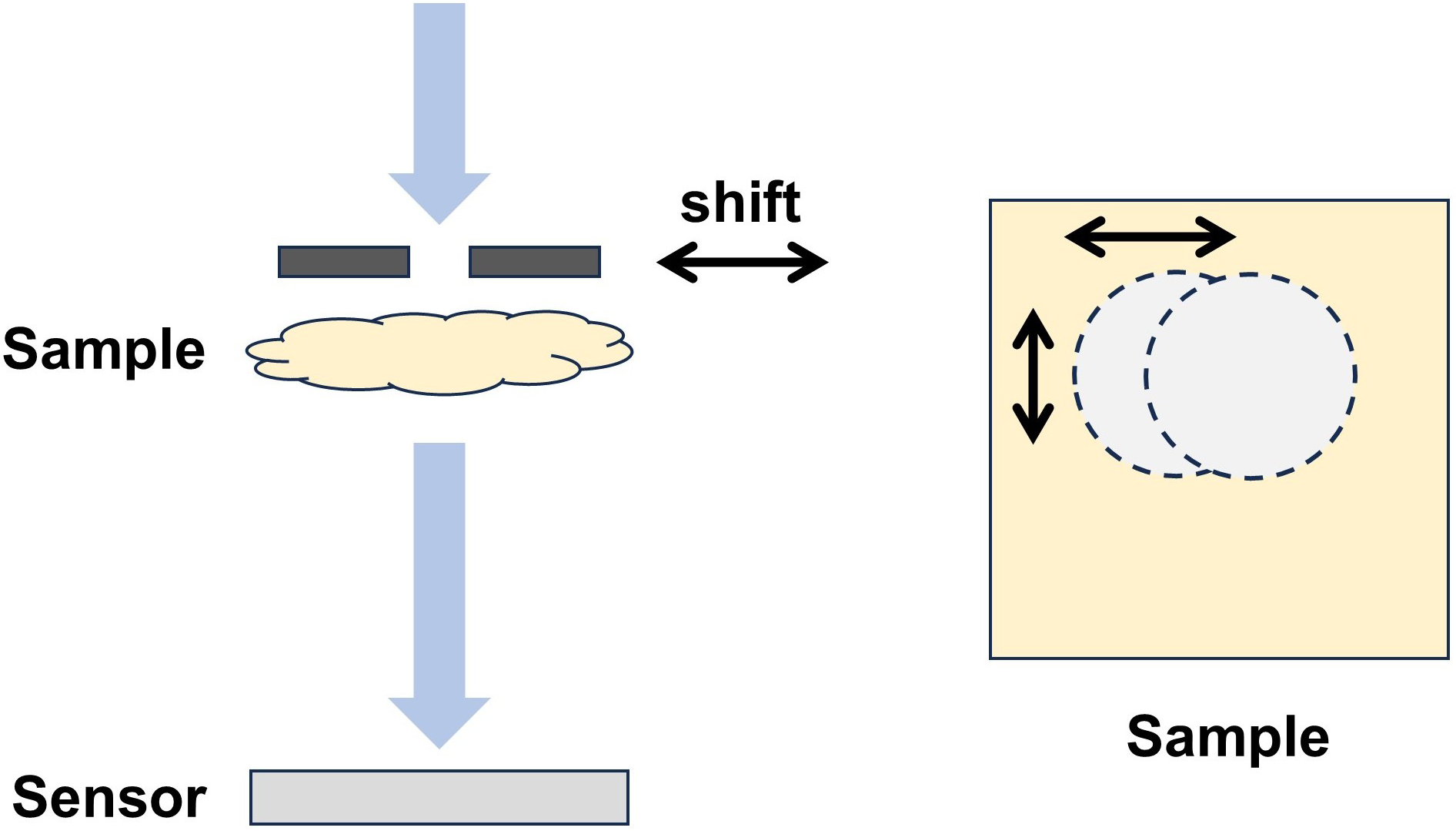
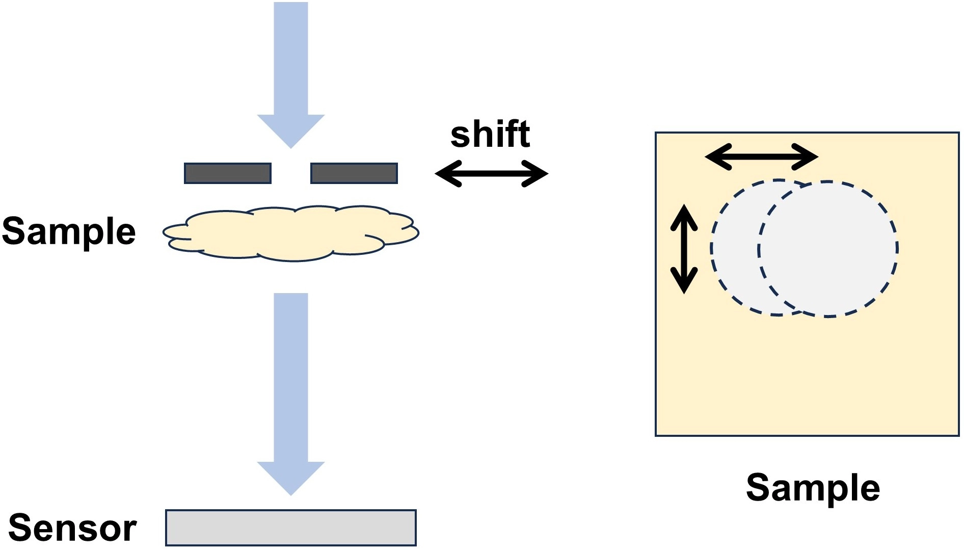
Figure 12. Schematic of overlap-constrained ptychographic scanning. A localized probe or aperture is translated across the sample, and adjacent scan positions share overlapping object regions that provide real-space redundancy.
4.1.3 Speckle-probe and scattering-medium diversity
Random scattering media generate fine structured fields that can function as information-rich illumination probes. Near-field ptychography demonstrated that a structured illumination field can be jointly recovered with the object from inline diffraction measurements, reducing the need for a separately calibrated probe[113]. Near-field Fourier ptychography further used speckle illumination to mix high spatial frequencies into the detectable band, with the effective resolution linked to the speckle feature size and the accessible scattering angles[114]. In contrast to full-field binary masks, speckle modulation naturally produces broadband spatial structure and can be implemented with a diffuser or scattering layer.
The advantage of an unknown speckle field is reduced calibration effort, but the inverse problem becomes more strongly coupled because both the object and illumination must be estimated. Reliable reconstruction requires sufficient speckle translation, overlap, and statistical diversity. Total variation (TV)-regularized speckle coded diffraction imaging reduced the required number of measurements by combining blind object-speckle recovery with an explicit piecewise-smooth prior; the reported simulations and experiments achieved high-fidelity reconstruction from 16 measurements[106]. This result illustrates the role of priors in reducing acquisition burden, but the attainable detail becomes dependent on the validity and strength of the regularization. Speckle-coded methods are therefore attractive for lensless and super-resolution phase retrieval, while diffuser drift, wavelength-dependent speckle decorrelation, and inaccurate propagation distance remain important sources of model mismatch. Figure 13 shows a representative near-field ptychographic configuration in which a structured field generated by a scattering element illuminates the sample before near-field diffraction detection.
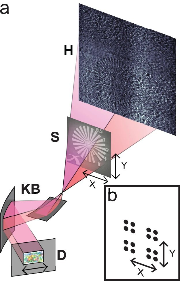
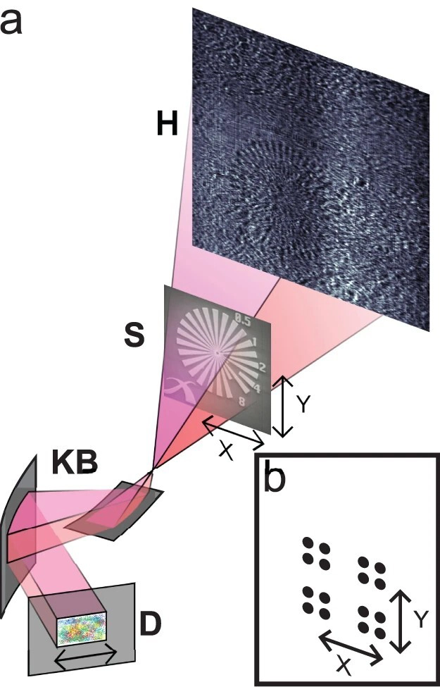
Figure 13. Near-field ptychography with structured illumination. Reproduced from reference[113]. CC BY 4.0. H: holographic image; S: sample; KB: Kirkpatrick-Baez optics; D: detector.
4.1.4 Angular and spectral illumination diversity
Angular illumination changes the incident wavevector and shifts different portions of the object spectrum into the passband of the imaging system. FPM uses a programmable LED array to record low-resolution intensity images under multiple illumination angles and iteratively stitches the corresponding Fourier-domain patches into a high-resolution complex image[19]. Quantitative phase recovery has been experimentally validated against theoretical samples and phase-shifting holographic measurements[115]. The principal advantage of FPM is its large space-bandwidth product: it combines the FOV of a low-numerical-aperture (NA) objective with a synthetic NA determined by the objective and illumination angles.
The main acquisition burden in conventional FPM is the large number of sequentially acquired intensity images. Multiplexed coded illumination activates multiple LEDs per exposure, reducing both the required number of camera frames and the total acquisition time. Each multiplexed frame is an incoherent sum of responses from several illumination angles, so reconstruction must disentangle these contributions within a more strongly coupled inverse problem[116]. This gain in acquisition efficiency can increase sensitivity to illumination-intensity errors and model mismatch. Quantitative FPM further depends on accurate calibration of illumination geometry and brightness, magnification, and the pupil function, including aberration and defocus; selected parameters may be jointly refined during reconstruction.
Fourier ptychographic diffraction tomography (FPDT) extends angular diversity to three-dimensional (3D) refractive-index reconstruction by combining bright-field and dark-field measurements in 3D Fourier space[117]. As shown in Figure 14, FPDT records intensity images with a low-NA objective under programmable LED illumination from different incident angles and iteratively fuses these measurements in 3D Fourier space to recover the volumetric refractive-index distribution. This expansion provides volumetric frequency coverage without interferometric complex-field acquisition, but many implementations rely on single-scattering or weak-object approximations. Strong multiple scattering, a limited angular range, and missing axial frequencies therefore define the practical boundary of FPDT. Spectral illumination provides an additional diversity dimension: multi-wavelength phase retrieval and wavelength-scanning lensless microscopy use wavelength-dependent propagation and sampling to strengthen reconstruction or pixel super-resolution[29,30,118]. Their benefit requires wavelength-resolved calibration of the source spectrum, mask response, aberration, and effective magnification.
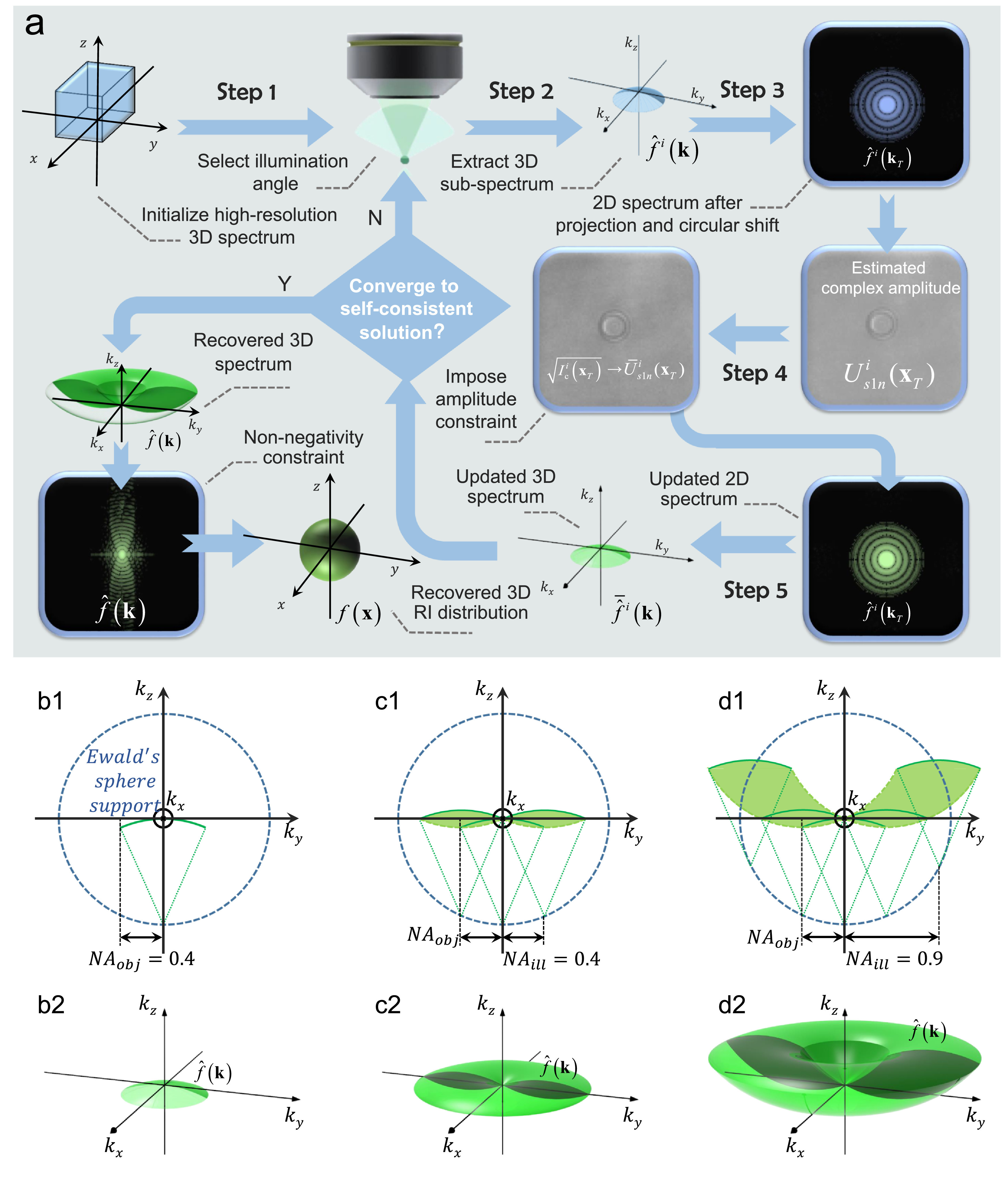
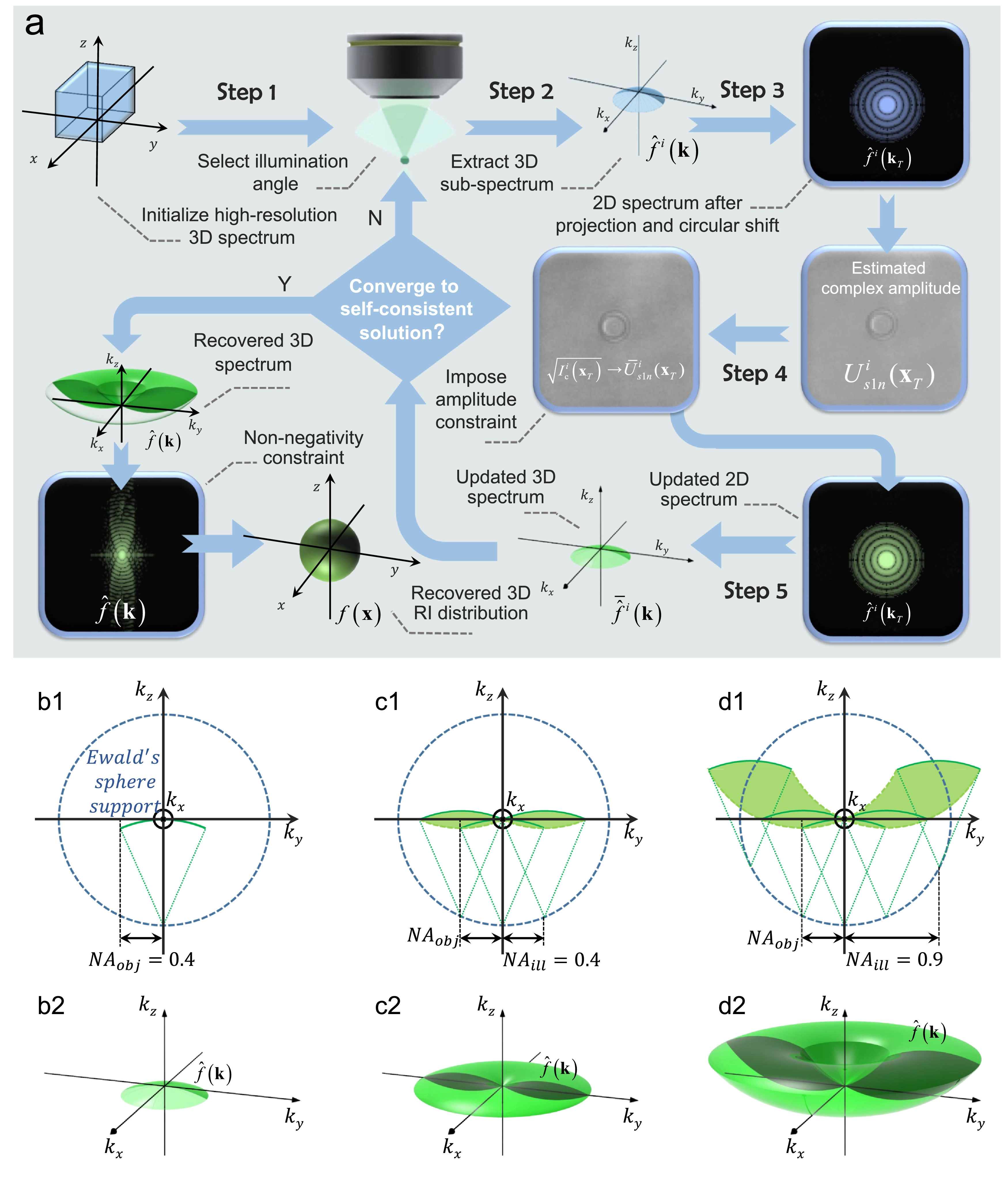
Figure 14. Angular-diversity illumination and 3D frequency coverage in FPDT. Reproduced from reference[117]. CC BY 4.0. 3D: three-dimensional; FPDT: Fourier ptychographic diffraction tomography.
4.2 Propagation modulation
Propagation diversity changes the axial evolution of the object wave rather than imposing a transverse coding pattern. The same exit wave produces different intensity distributions at different propagation distances, defocus states, or wavelengths. This route is optically simple because it can be implemented by translating the detector or sample, changing focus, or switching wavelength. Its information content, however, depends strongly on the selected plane spacing: planes that are too close may provide nearly redundant intensities, whereas excessive propagation can cause field expansion, aliasing, reduced signal, or loss of common FOV.
The TIE provides a deterministic small-defocus formulation. Under paraxial conditions, the axial intensity derivative is related to the transverse phase gradient, enabling phase recovery from a focused image and nearby defocused images[16,88,90]. TIE is computationally efficient and avoids random initialization, but its quantitative accuracy depends on the finite-difference approximation of the axial derivative, boundary conditions, intensity zeros, small-defocus validity, and accurate registration. It is therefore best suited to slowly varying phase objects and moderate NA values rather than arbitrary strongly diffracting fields.
Multi-plane iterative phase retrieval removes the small-defocus linearization and alternates propagation among several measured planes with amplitude replacement. Single-beam multiple-intensity reconstruction (SBMIR) used a 3D volumetric speckle field and sequential axial intensity measurements to reconstruct the complete wavefront[89]. Holographic illumination can further increase differences among axial measurements and mitigate stagnation when plane-wave propagation produces weak intensity variation[91]. These methods provide stronger nonlinear constraints than TIE, but they require repeated exposures and are sensitive to propagation-distance error, lateral registration, magnification change, illumination drift, wavelength uncertainty, and detector sampling mismatch.
Propagation and wavelength diversity should therefore be distinguished from purely computational regularization. The additional planes or wavelengths are physical measurements that alter the forward operator and can encode information not present in a single intensity image. Their main application boundary is temporal: sequential axial or spectral acquisition is effective for static and slowly varying specimens, whereas snapshot dynamic imaging generally requires spatial multiplexing or a fixed coding element that records sufficient diversity in one exposure. A representative multi-plane implementation with holographic illumination is shown in Figure 15; a computer-generated hologram increases the diversity among the axially recorded diffraction patterns.
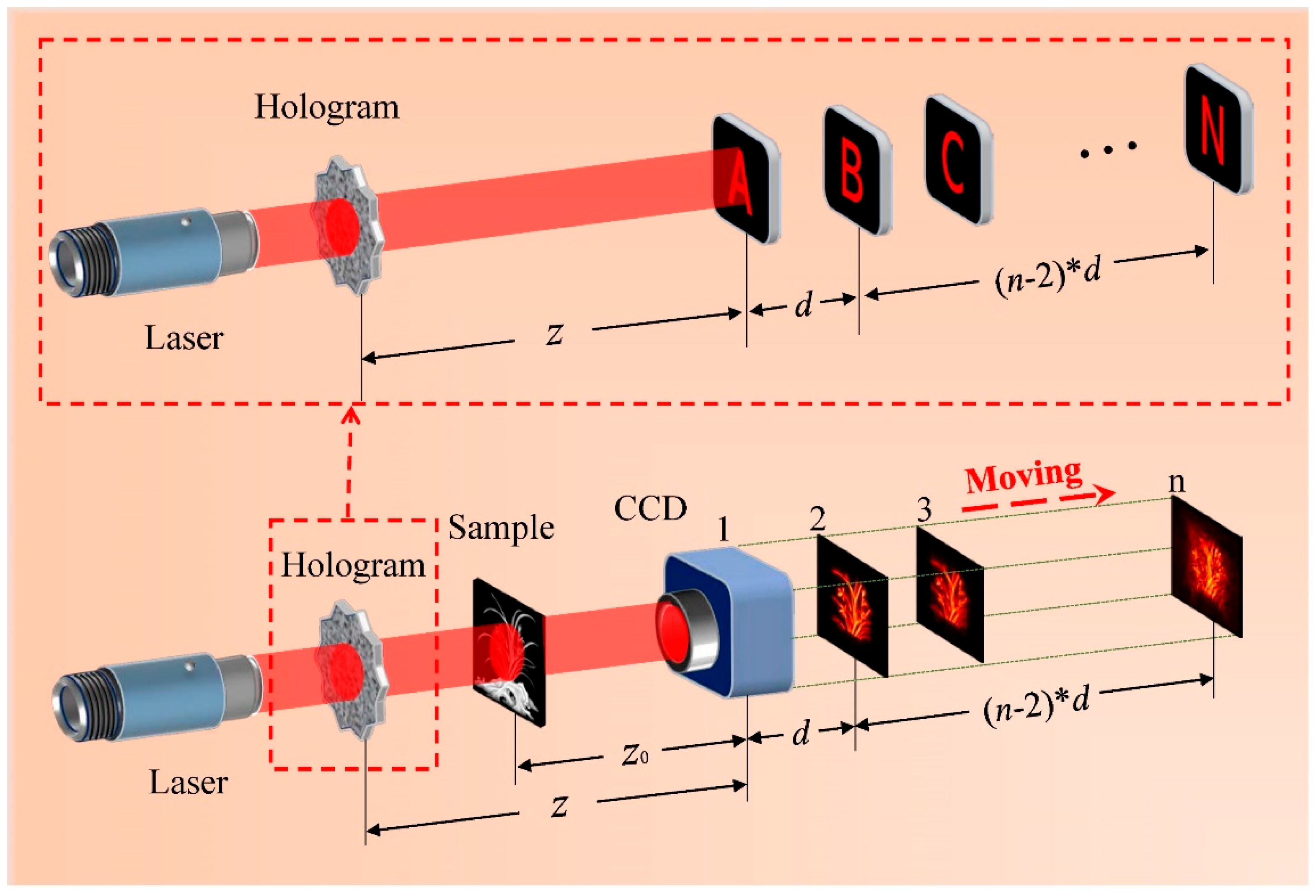
Figure 15. Multi-plane phase retrieval using holographic illumination. A computer-generated hologram forms distinct illumination patterns at successive axial planes, and the camera is translated to record the corresponding diffraction intensities. Reproduced from reference[91]. CC BY 4.0. CCD: charge-coupled device.
4.3 Detection-side and sensor-integrated modulation
Detection-side modulation encodes the object exit wave after it has interacted with the specimen. A coded aperture, phase plate, wavefront modulator, diffuser, or sensor-integrated scattering layer changes the field before intensity detection. Because the sample illumination can remain fixed, detection-side coding is attractive for compact and potentially single-shot systems. The principal design problem is to generate sufficiently informative intensity variation without blocking excessive optical power or making the forward model too sensitive to fabrication and alignment errors.
4.3.1 Coded-aperture modulation
Single-shot phase imaging with a coded aperture demonstrated that a known random aperture can provide support-like constraints for reference-free phase retrieval from one intensity image[119]. Subsequent work relaxed the original low-transmission binary design to include high-transmission amplitude, phase-only, and complex-amplitude masks[120]. This development is important because mask transmittance and modulation strength have competing effects: a highly opaque aperture can create strong constraints but removes object photons and spatial-frequency content, whereas a weakly modulating aperture preserves throughput but may not sufficiently condition the inverse problem.
Coded-diffraction reconstruction has also been combined with subpixel models and sparse regularization to recover information beyond the detector pixel pitch[121]. Related lensless systems using stationary random phase masks similarly encode subpixel structure into measurable diffraction patterns[122]. In these cases, super-resolution does not arise from numerical interpolation alone; it relies on a calibrated subpixel variation in the optical response and on a forward model that accurately represents pixel integration and propagation.
A coded aperture can additionally constrain joint recovery through unknown aberrations. In single-shot blind deconvolution, a known pupil-plane aperture reduces the degrees of freedom of the unknown aberrated pupil and allows the object and pupil function to be estimated from one coded intensity measurement[123]. The limitation is that the aperture itself removes part of the spectrum, so object support, sparsity, or TV regularization becomes important. Coded apertures are therefore most useful when compact single-shot operation is more important than maximum photon throughput and when the mask response can be accurately characterized. The coded-aperture blind-deconvolution configuration is shown in Figure 16, where the known binary aperture is positioned at the pupil plane to constrain the unknown aberrated pupil.
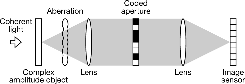
Figure 16. Single-shot CDI through an unknown aberration with a known coded aperture placed in the pupil plane. Reproduced from reference[123]. CC BY 4.0. CDI: coherent diffraction imaging.
4.3.2 Known wavefront modulation and CMI
Known wavefront modulation represents the coding element as a calibrated complex-valued operator in the propagation model. Aperture-plane phase modulation with a laterally shifted phase plate introduced multiple known diffraction states and improved phase-retrieval convergence for arbitrary complex-valued fields[124]. The same principle was extended to X-ray CDI, where phase-front modifications supplied diversity and reduced reliance on a sharply known object support[125]. Randomly coded masks combined with convex-relaxation and iterative refinement further demonstrated that a small number of known mask states can lead to reproducible convergence[126].
CMI places a fixed known modulator between the object and detector and reconstructs the object from the resulting modulated diffraction pattern[38]. In contrast to shifted-mask methods, the calibrated modulator can encode the exit wave in a single exposure. The single-shot CMI result directly supports the use of calibrated post-object coding when a repeatable multi-frame sequence is difficult to obtain[38]. More broadly, CDI at short wavelengths has also been extended to pulsed and ultrafast measurements using related single-exposure constraints[24,53,127]. Extended CMI has further addressed artifacts associated with an imperfect or structured illumination field by separating object and illumination contributions in the reconstruction model[128].
The snapshot advantage of CMI should not be interpreted as unconditional uniqueness. Reconstruction still depends on detector sampling, modulator feature size and distance, object support or other priors, and sufficiently accurate knowledge of the modulator complex response. Small errors in modulator phase, propagation distance, wavelength, or lateral registration can be repeatedly reinforced by iterative propagation and produce structured artifacts. High-transmission phase coding is preferable in low-dose applications, but phase-only elements are more dispersive and difficult to calibrate over broad spectral ranges. Known wavefront modulation is therefore most compelling when single-exposure acquisition is essential and system calibration can be maintained. Figure 17 illustrates the CMI geometry, in which a calibrated modulator placed downstream of the object encodes the exit wave before far-field detection.
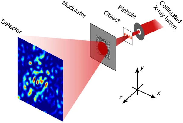
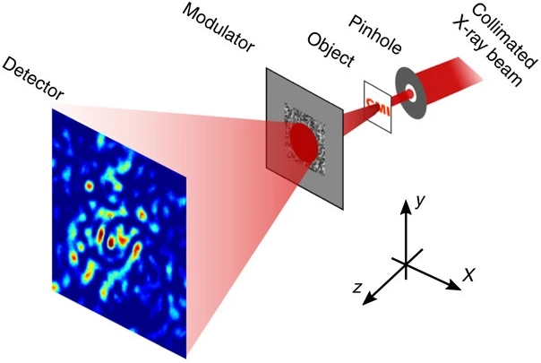
Figure 17. CMI configuration with a calibrated post-object modulator and a far-field detector. Reproduced from reference[38]. CC BY 4.0. CMI: coherent modulation imaging.
4.3.3 Sensor-integrated coded modulation
Sensor-integrated modulation places a diffuser, coded layer, or engineered scattering surface close to or directly on the detector. The short object-to-sensor distance enables compact lensless systems and allows otherwise inaccessible angular or subpixel information to be mixed into the measured intensity. Near-field blind ptychographic modulation reconstructs the object and an unknown diffuser response from translated measurements, providing wide-field, high-resolution lensless phase imaging[129]. Angle-tilted and wavelength-multiplexed ptychographic modulation adds angular and spectral diversity for multispectral lensless microscopy[130], while coded image sensors combine multi-height data with estimation of the sensor coding response[131].
Ptychographic sensors have also been developed for large-scale microbial monitoring with temporal-similarity constraints[132]. Resolution-enhanced parallel coded ptychography integrates a disorder-engineered surface with the image sensor so that high-angle scattering is converted into detectable coded intensity variation[39]. The fixed coding layer reduces repeated alignment and probe-calibration effort and is compatible with high-throughput operation. However, these systems often still require sample translation, multiple heights, or other diversity; sensor integration therefore does not automatically imply snapshot acquisition.
The dominant challenges are manufacturing variation, the spacing between the coded layer and sensor, angle- and wavelength-dependent response, pixel-response nonuniformity, and long-term contamination or drift. When the coding response is estimated jointly with the object, the system becomes self-calibrating but more weakly identifiable. Comparable detector constraints also motivate coded and computational architectures in non-visible bands such as terahertz imaging, where focal-plane arrays have historically been more limited than visible-light sensors[54]. Sensor-integrated coding is therefore best viewed as an alignment-stable hardware platform whose performance depends on the available acquisition diversity and calibration model. A representative sensor integrated implementation is shown in Figure 18, where a disorder-engineered surface directly above the pixel array converts high-angle scattering into measurable coded intensity while a clear region supports positional tracking.
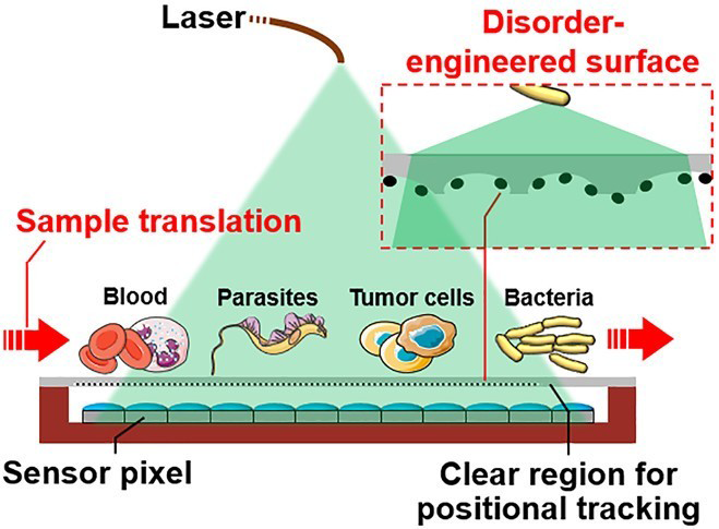
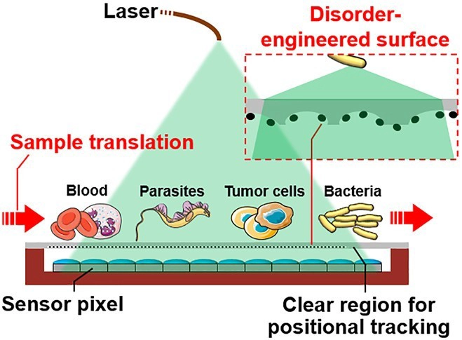
Figure 18. Resolution-enhanced parallel coded ptychography using a disorder-engineered surface integrated with the image sensor for high-throughput lensless imaging. Reproduced with permission from reference[39]. Copyright © 2021 American Chemical Society.
4.4 Reconstruction and calibration of modulated measurements
Physical modulation improves phase observability only when the reconstruction model correctly incorporates the implemented illumination, propagation, coding, and detector response. The computational problem should therefore be formulated as inversion of a modulated forward model rather than as an isolated phase-retrieval routine. Figure 19 summarizes the common reconstruction loop: the current object and system-parameter estimates are propagated through each modulation state, compared with the measured intensities, and updated under data-consistency, regularization, and calibration constraints. Learning modules can be inserted as an initialization, prior, denoiser, or direct inverse, but they do not replace the need for physically informative measurements.
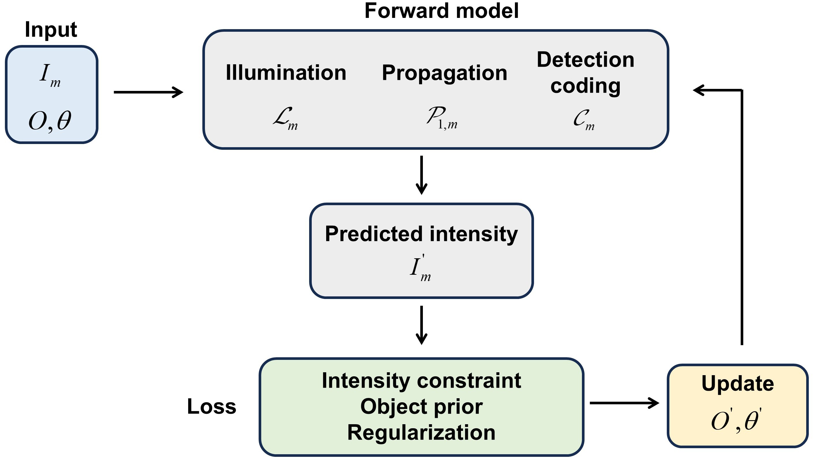
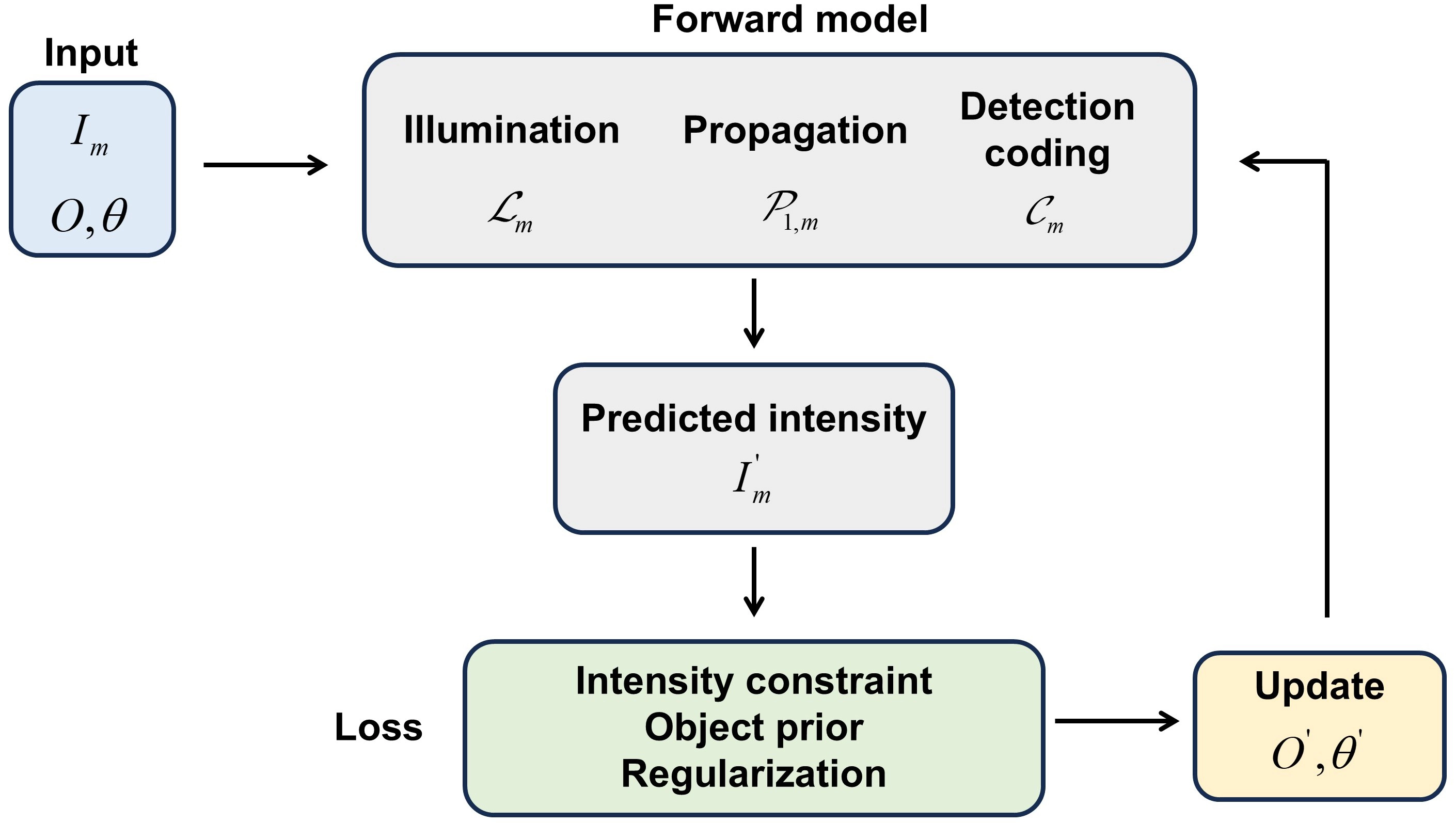
Figure 19. Unified reconstruction, joint calibration, and learning-assisted inversion framework for modulated diffractive imaging.
4.4.1 Physics-model-based reconstruction and optimization methods
Classical GS, error-reduction (ER), and hybrid input-output (HIO) algorithms alternate between object and detector domains while enforcing measured amplitude and object-domain constraints[18,133,134]. Modulated diffraction imaging generalizes this procedure by replacing a single Fourier transform with the appropriate state-dependent operator. A common optimization form is
where A contains the illumination, propagation, coding, and detector operators; θ denotes unknown system parameters; L is a data-fidelity term; λ is the regularization parameter controlling the weight of R(O), and R(O) is an object prior. Alternating-projection methods effectively impose a hard measured-amplitude constraint, whereas gradient or proximal algorithms minimize an explicit intensity- or amplitude-domain objective. TV, sparsity, support, positivity, and spectral or inter-slice consistency can be introduced through R(O)[106,121,123].
The appropriate data term depends on the noise regime. Least-squares amplitude or intensity losses are convenient under moderate approximately Gaussian noise, while low-count X-ray, electron, or photon-limited measurements are more accurately represented by a Poisson likelihood. Maximum-likelihood refinement provides a statistically grounded way to weight diffraction data and improve robustness to photon-counting noise[135]. The same principle can be combined with ptychographic overlap, coded masks, or multi-plane propagation, although the computational cost increases because each iteration must evaluate many large-scale propagation operators.
Different named algorithms mainly differ in how Equation (10) is split and updated. PIE-type methods use local object and probe updates[61,109-111]; FPM updates overlapping Fourier patches and often estimates the pupil[19,115,116]; CMI alternates propagation through a known modulator and detector-amplitude constraints[38,128]; and multi-plane methods sequentially enforce intensities at different axial positions[89,91]. Their common limitation is model dependence: fast convergence to a small residual does not guarantee quantitative accuracy when the assumed forward operator is wrong.
4.4.2 Blind reconstruction, self-calibration, and model mismatch
Calibration errors are especially important in diffractive imaging because modulation increases both information content and model complexity. Unknown probe fields, mask responses, pupil aberrations, scan positions, propagation distances, wavelength errors, detector gain, and partial coherence can all be coupled with the object estimate. Joint recovery reduces the need for separate calibration, but it also introduces gauge freedoms and ambiguities. For example, object and probe can exchange slowly varying amplitude or phase factors, and an inaccurate distance can be partially absorbed into object phase curvature.
Ptychographic overlap often provides enough redundancy to update the probe and object simultaneously[61,111], and position-refinement algorithms can estimate scanning errors[62,112]. Coded-aperture blind deconvolution estimates an unknown pupil under a known support-like aperture[123], while extended CMI separates illumination artifacts from the object[128]. For partially coherent or unstable illumination, mixed-state reconstruction models the recorded intensity as an incoherent sum of several mutually incoherent modes rather than forcing all data into a single coherent probe[136]. This treatment improves physical fidelity but increases the number of unknown fields and requires sufficient data diversity to distinguish meaningful modes from noise.
Self-calibration should therefore be introduced selectively. A calibrated model has fewer degrees of freedom and is preferable when stable calibration data are available. Blind recovery is valuable when the modulation changes during operation or cannot be measured independently, but unrestricted joint estimation can fit noise and hide systematic errors. Practical reconstruction should combine independent calibration, bounded parameterization, regularization, and residual analysis. Reporting only the final image is insufficient; quantitative studies should also report the estimated mask or probe, refined positions or distances, data residuals, and uncertainty or repeatability across independent initializations.
4.4.3 Learning-assisted reconstruction
Deep learning contributes to modulated phase retrieval in four main ways: fast direct inversion, learned initialization, learned regularization or denoising, and physics-constrained parameterization. These roles should be distinguished because they have different requirements and failure modes[43]. Table 4 summarizes the principal categories.
Table 4. Functional comparison of learning-assisted reconstruction strategies.
| Learning role | Representative works | Physical data consistency | Main contribution | Principal risk |
| Supervised end-to-end inversion | FPM network; PtychoNN | Usually implicit or applied only during training | Very fast inference after training; can reduce sampling burden | Requires representative paired data; vulnerable to domain and system shift |
| Physics constrained/self-supervised optimization | Untrained phase imaging; physics-driven CMI; physics-informed FPM; unsupervised ptychography | Explicit differentiable forward model | No measured phase labels; preserves measurement consistency | Per-data-set optimization can be slow; remains sensitive to model mismatch |
| Deep prior/plug-and-play regularization | prDeep; deep-prior diffraction tomography; DPD | Explicit iterative data fidelity with learned or untrained prior | Improved noise robustness and reduced artifacts under sparse data | Prior can bias fine structure or fit noise; parameter tuning remains important |
| Hybrid calibration and correction | Network-assisted aberration, illumination, or residual correction | Physical inversion remains the main reconstruction path | Targets specific model errors without discarding interpretability | Correction may fail outside the trained error range and can conceal calibration defects |
CMI: coherent modulation imaging; FPM: Fourier ptychographic microscopy; DPD: deep phase decoder.
Supervised end-to-end methods learn a direct mapping from measured intensities to object phase or complex amplitude. Networks have reconstructed high-resolution FPM images from multi-angle low-resolution inputs[137], and PtychoNN predicts local object amplitude and phase from diffraction measurements at substantially higher inference speed than conventional iterative reconstruction[138]. These methods are attractive for real-time or high-throughput operation after training, but their output is governed by the training distribution. Changes in specimen type, wavelength, magnification, noise statistics, illumination, or coding response can lead to degraded or physically inconsistent reconstructions.
Physics-constrained methods reduce dependence on paired ground truth by embedding the diffraction model into the loss. Untrained neural networks have been optimized directly from a measured intensity image[63], physics-driven networks have incorporated the CMI forward model and aperture constraints[139], and physics-informed FPM has combined sparse angular measurements with a differentiable image-formation model[64]. Physics-constrained unsupervised learning has also been applied to scanning coherent diffraction reconstruction[140]. These approaches preserve data consistency more explicitly than a purely supervised inverse, but they usually require iterative optimization for each measurement set and remain sensitive to errors in the embedded physical model. The PhysenNet workflow is illustrated in Figure 20; the network-estimated phase is propagated through the physical diffraction model, and the resulting intensity mismatch is used to update the untrained network.
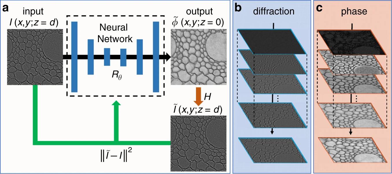
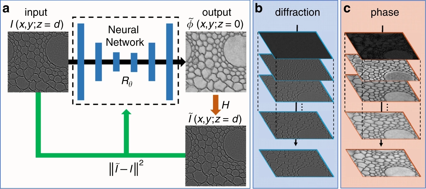
Figure 20. Physics-constrained phase-retrieval workflow of PhysenNet. (a) A measured diffraction pattern is fed to an untrained neural network to estimate the object phase. The estimated phase is propagated through the physical diffraction model to generate a predicted intensity, and the intensity mismatch is minimized to update the network parameters; (b,c) Evolution of the predicted diffraction pattern and recovered phase during optimization. Reproduced from reference[63]. CC BY 4.0.
Deep-prior and plug-and-play methods use a network as a regularizer rather than as the complete inverse. prDeep combines a flexible denoising network with a phase-retrieval data term and improves robustness under different noise levels and measurement matrices[141]. Deep-prior diffraction tomography constrains a 3D refractive-index distribution using an untrained network[142], while the DPD jointly represents object phase and Zernike aberrations for self-calibrated phase microscopy[143]. These methods can reduce noise and undersampling artifacts, but the recovered structure reflects both the measurement and the chosen prior. Quantitative applications therefore require uncertainty analysis and validation against independently measured features.
The boundary of learning-assisted inversion is the information encoded by the measurement. A network can exploit correlations, compensate residual errors, and accelerate optimization, but it cannot reliably create unmeasured spatial frequencies or phase information without introducing prior-dependent content. The most defensible direction is therefore hybrid: optical modulation should first produce informative and well-conditioned measurements; the reconstruction should preserve explicit data fidelity; and learning should be used for initialization, regularization, calibration, or uncertainty-aware acceleration rather than as an unconstrained substitute for the forward model.
In summary, diffractive modulation improves complex-field recovery through three complementary physical routes. Illumination-side strategies provide coded, overlapping, speckle, angular, or spectral diversity; propagation diversity uses axial or wavelength-dependent field evolution; and detection-side strategies encode the exit wave with apertures, modulators, or integrated structures. Sequential methods generally provide strong and separable constraints but are limited by acquisition time and motion, whereas snapshot coding improves dynamic adaptability at the cost of greater calibration sensitivity and reduced redundancy. Across all routes, reconstruction reliability is determined jointly by the independence of the modulation states, optical throughput, detector sampling, noise statistics, and consistency between the physical system and computational model.
5. Cross-Strategy Comparison and Method Selection
The preceding sections classified optical-field modulation according to its physical position and role in the imaging chain. Method selection, however, requires a system-level comparison that extends beyond the modulation element itself. Spatial performance, phase uncertainty, FOV, acquisition time, photon use, hardware requirements, reconstruction burden, calibration stability, and tolerance to specimen motion are coupled. Increasing measurement diversity can improve phase observability and reconstruction robustness, but it can also increase the number of exposures, accumulated dose, calibration parameters, and computation. Conversely, snapshot encoding reduces inter-frame inconsistency but usually shares finite detector bandwidth, spatial sampling, or photon budget among several information channels. The relevant question is not which method is universally superior, but which measurement design provides sufficient independent information under the dominant constraints of a particular experiment.
5.1 Common comparison criteria
A direct numerical ranking of phase-imaging methods is rarely defensible because reported values are obtained with different wavelengths, NAs, detector formats, specimens, noise levels, and resolution criteria. Spatial performance may be reported as half-pitch resolution, line width, reconstructed feature size, or effective NA. Temporal performance may denote exposure duration, raw acquisition time, modulation rate, reconstructed-field rate, or end-to-end latency. Likewise, signal-to-noise ratio may refer to raw intensity, reconstructed amplitude, or recovered phase.
Hardware cost is also difficult to compare reproducibly across laboratories and publication years. Therefore, we use identifiable hardware requirements as proxies for system complexity, including the number of interferometer arms, active modulators, scanning axes, specialized detectors, polarization components, and coded elements. A device refresh rate is not treated as an imaging rate unless the complete set of measurements required for one reconstructed field is included. Table 5 summarizes representative experimental operating points and their system level boundaries rather than presenting normalized benchmarks or a universal ranking.
Table 5. Representative reported operating points and system-level boundaries of modulation-enabled phase-imaging methods.
| Method | Reported performance | Reported acquisition protocol | Hardware |
| Four-shot phase-shifting Mach-Zehnder interferometry (MP-MZI)[59] | Temporal stability/spatial sensitivity: 18.95/27.76 mrad | Four sequential holograms per reconstructed field. | dual-path Mach-Zehnder interferometer, phase stepping, and camera; vulnerable to vibration, drift, intensity fluctuation, and phase-step error |
| Single-shot polarization phase-shifting Mach-Zehnder interferometry (PP-MZI)[59] | Temporal stability/spatial sensitivity: 12.20/24.86 mrad | One exposure; four polarization channels. | dual-path Mach-Zehnder interferometer, polarization optics, and polarization camera; requires extinction-ratio and channel-registration calibration |
| Single-shot Fizeau polarization phase-shifting digital holography (FP-PSDH)[59] | Temporal stability/spatial sensitivity: 4.02/17.47 mrad; 57.0 line pairs/mm | One exposure; four polarization channels (0.1-s sampling in the stability test) | Single-path Fizeau with polarization optics/camera; sampling and accuracy depend on channel calibration |
| Holographic-illumination propagation diversity[91] | 24.8-μm features; depth 454.4-457.7 nm vs 477 nm (≈ 4.5% error) | Four planes at 2-mm intervals; static targets. | SLM, axial detector scan, and CCD; motion and distance/stage error limit dynamic use |
| DMD-scanned high-speed FPM[144] | ≈ 1-μm lateral resolution; nanometre-scale RBC membrane-height sensitivity | > 42 reconstructed fields/s in the reported configuration. | Laser, DMD, objective, and camera; angle, pupil, coherence, and timing calibration required |
| High-throughput Single-pixel compressive holography[96] | 256 × 256 pixels; SBP-T 41,667 pixels/s; 5.80 × 4.31 μm resolution over 1.49 × 1.11 mm FOV; phase error ≈ 0.104 rad | 65,536 patterns (≈ 3 s); acceptable recovery at ≥ 12.5% sampling under the tested noise condition | DMD, two AOMs, synchronization, and single-pixel detector; sequential patterns, so DMD rate ≠ field rate |
| Ptychography[61] | Joint object-probe recovery; comparable resolution and frame rate were not reported | 100 overlapping positions; one diffraction pattern per position | Coherent probe, precision scan, and detector; scan time, dose, position error, and iteration limit dynamics |
| TV-regularized speckle-coded diffraction imaging[106] | Joint object-speckle recovery; comparable resolution and phase noise were not reported | 16 images versus hundreds for the compared alternating-projection method | Translated diffuser and diffraction detector; sensitive to diffuser shift, distance, and TV prior |
| Resolution-enhanced parallel coded ptychography[39] | 308-nm line width over a 240-mm2 effective FOV | Gigapixel-scale data acquired in 15 s. | Coded surfaces, eight sensors, and sample translation; high throughput, not snapshot acquisition |
| X-ray CMI[38] | Estimated resolution: 37 nm; modulator transmission ≈ 70% | Local recovery: one 3-s exposure and 150 iterations; larger FOV: 12 × 5 overlapping positions. | 6.2-keV source, calibrated tungsten modulator, and detector; code calibration, local FOV, probe stability, and reconstruction time remain limiting |
SLM: spatial light modulator; DMD: digital micromirror device; FPM: Fourier ptychographic microscopy; RBC: red blood cell; SBP-T: space-bandwidth-time product; FOV: field of view; AOMs: acousto-optic modulators; TV: total variation; CMI: coherent modulation imaging; MZI: Mach-Zehnder interferometry; MP-MZI: multiple-shot phase-shifting MZI; PP-MZI: single-shot polarization phase-shifting MZI; FP-PSDH: Fizeau polarization phase-shifting digital holography; CCD: charge-coupled device.
The matched comparison in the first three rows isolates an important interferometric trade-off. Under the conditions of Ref.[59], replacing sequential four-shot detection with polarization multiplexing reduced inter-frame sensitivity, while the single-path Fizeau configuration produced lower temporal and spatial phase fluctuations than the two Mach-Zehnder configurations. This result should be presented as evidence from one controlled comparison, not as a universal ranking of all temporal and snapshot interferometers. Other reported operating regimes include multi-plane holographic illumination, high-speed FPM, and single-pixel holography[91,96,144]. Ptychography, speckle-coded CDI, parallel coded ptychography, and X-ray CMI provide complementary examples[38,39,61,106]. Their numerical values remain conditional on the reported wavelength, sample, detector, acquisition protocol, and reconstruction criterion.
Specific operating points do not by themselves provide a method-selection rule. Table 6 compares method classes according to the diversity mechanism, reconstruction burden, calibration requirements, and application boundary. The computational categories are nominal: implementation, data size, hardware acceleration, stopping criterion, and joint calibration can change the actual runtime by orders of magnitude.
Table 6. Reconstruction, calibration, and application boundaries of representative phase-imaging method classes.
| Method | Measurement diversity and acquisition | Reconstruction strategy and nominal burden | Calibration and model dependencies | Suitable conditions and limitations |
| Temporal phase shifting[20,67,68] | ≥ 3 sequential reference-phase states | Linear or generalized least-squares demodulation (low) | Phase steps, intensity/gain, and reference stability | Static metrology and traceable recovery; motion/drift corrupt the sequence |
| Off-axis and common-path holography[15,21,22] | One spatial-carrier or self-reference exposure. | Fourier filtering and propagation (low). | Carrier/window, reference curvature, and self-reference contamination | Single-exposure dynamic QPI; sideband separation consumes detector bandwidth |
| Snapshot multiplexed phase shifting[59,60,69] | Several spatial/polarization channels in one exposure | Channel extraction, interpolation, and demodulation (low) | Extinction ratio, retardance, gain, crosstalk, and registration | Rapid specimens; divides spatial sampling and photon budget among channels |
| Propagation diversity[86,89,91] | ≥ 2 defocused or axially separated planes | Iterative propagation and constraints (moderate-high) | Distance, wavelength, magnification, registration, and illumination | Compact reference-free imaging; axial scanning and distance error limit dynamics |
| FPM[19,115,116,144] | Multiple illumination angles; optional multiplexing or rapid scan | Fourier-patch synthesis with optional pupil recovery (high) | Angle/intensity, pupil, coherence, and 2D/3D sample model | Large FOV and synthetic NA; conventional acquisition is multi-frame and motion sensitive |
| Ptychography[61,62,111] | Overlapping probe positions; one pattern per position | Object, probe, and position updates (high) | Probe or pupil, scan positions, propagation geometry, detector response, and partial coherence | Very high-resolution imaging, including X-ray and electron applications; scan time, accumulated dose, and computation limit nonrepeatable dynamics |
| Speckle- or diffuser-coded CDI[106,113,114] | Several translated or changed speckle states | Blind/regularized object-probe recovery (high) | Speckle, shift, wavelength, distance, and regularization | Compact lensless imaging; generally multi-frame and prior dependent |
| Single-pixel and compressive holography[92,94,96] | Sequential patterns measured by a bucket detector | Transform or compressed reconstruction (moderate-high) | Synchronization, gain, modulation fidelity, drift, and prior | Useful where array detectors are unsuitable; sequential projection is not snapshot |
| CMI and coded-aperture phase retrieval[38,119,128] | One or several post-object coded diffraction measurements | Iterative propagation through known or estimated code (moderate-high) | Code transmission, illumination, distance, support, and detector | Local single-exposure recovery; FOV and accuracy depend on code calibration |
| Sensor-integrated coding and coded ptychography[39,129,131,132] | Near-sensor code, often with translation or multi-height diversity | Iterative object recovery with a calibrated or jointly refined probe/coding response, depending on the implementation (high) | Code response/spacing, pixel response, wavelength, and motion. | Compact, high-throughput platforms; integration does not guarantee snapshot acquisition |
The reported computational burden is qualitative and nominal; actual runtime depends on data size, implementation, hardware acceleration, stopping criteria, and joint-calibration requirements. QPI: quantitative phase imaging; FPM: Fourier ptychographic microscopy; 2D: two-dimensional; 3D: three-dimensional; FOV: field of view; NA: numerical-aperture; CDI: coherent diffraction imaging; CMI: coherent modulation imaging.
5.2 Unified comparison of mainstream methods
Interferometric strategies provide the most direct conversion from object phase to measured intensity because the object field is mixed with a known or self-generated reference. Temporal phase shifting supports well-conditioned demodulation and low computational cost when the phase steps are calibrated[20,67,68], but its accuracy is conditional on specimen and interferometer stability throughout the sequence. Off-axis holography replaces temporal diversity with a spatial carrier[21,22]; DPM uses a common-path self-reference to improve stability[15]. Both support single-exposure recovery, but the zero order, desired cross term, and conjugate term must remain separable within the detector bandwidth. Snapshot polarization or spatial multiplexing also removes inter-frame motion[59,60,69], while introducing channel-dependent sampling, crosstalk, and calibration errors.
Reference-free diffractive methods obtain phase observability from propagation, illumination, scanning, or coding diversity. Multi-plane methods require limited additional optics but are directly affected by axial motion and propagation-distance error[86,89,91]. FPM expands the effective NA while retaining the FOV of a low-NA objective[19,115,116]; programmable angle scanning can substantially increase the reconstructed-field rate under a specific configuration[144], but the reported rate remains conditional on the required angular data, detector timing, and reconstruction implementation. Ptychography uses overlap redundancy to recover the object and probe and to refine selected system parameters[61,62,111]. That redundancy improves conditioning but increases scan time, accumulated dose, and computation, making conventional ptychography better suited to static high-resolution measurements than to nonrepeatable events.
Speckle and detection-side coding occupy an intermediate design space. Translated speckle fields provide information-rich probes, but blind reconstruction couples object structure to diffuser and shift estimates[106,113,114]. Single-pixel holography trades parallel detector sampling for sequential pattern projection and is most competitive when suitable detector arrays are unavailable or prohibitively expensive[92,94,96]. Static post-object coding, including CMI and coded apertures, can support local single-exposure recovery[38,119,128]. Sensor-integrated coding improves mechanical compactness and repeatability[39,129,131,132], but fabrication error, code-sensor spacing, pixel response, and any required translation remain part of the forward model. In all three cases, optical compactness transfers rather than eliminates calibration and computational burden.
5.3 Application-oriented method selection
For static metrology and slowly varying specimens, temporal phase shifting is preferred when phase accuracy, transparent demodulation, and low reconstruction cost are more important than acquisition speed. Propagation diversity is appropriate when a reference arm is undesirable and several accurately registered axial measurements can be acquired. For rapidly varying or nonrepeatable events, off-axis holography, common-path holography, snapshot phase shifting, and genuinely single-exposure coded diffraction are more appropriate. Their snapshot advantage must nevertheless be evaluated together with exposure duration, detector readout, optical throughput multiplexing loss, calibration overhead, and reconstruction latency; one raw detector frame is not automatically equivalent to real-time phase imaging.
When a large space-bandwidth product is required, FPM provides a practical compromise between FOV and synthetic NA. Ptychography is preferable when the highest spatial resolution, robust overlap constraints, or compatibility with X-ray and electron wavelengths outweigh acquisition time and dose. Speckle-coded and sensor-integrated methods are attractive for compact lensless systems when the coding response can be calibrated or jointly estimated. Single-pixel holography is most competitive at wavelengths where suitable detector arrays are unavailable or prohibitively expensive, provided that the cost of sequential pattern acquisition is acceptable. CMI is attractive when a stable post-object modulator can encode sufficient spatial diversity within a single local exposure.
Therefore, the preferred design is not the one with the largest number of modulation states, but the one that provides sufficiently independent measurements without repeatedly dividing or discarding the available photon budget. As summarized in Figure 21, the dominant experimental constraint should determine the route: temporal consistency favors snapshot interferometry or single-exposure coding; large FOV and synthetic aperture favor FPM; extreme resolution and short wavelengths favor ptychography or CDI; detector scarcity favors single-pixel architectures; and traceable static metrology favors calibrated interferometric demodulation. This decision guide is not a universal ranking because specimen dynamics, wavelength, detector technology, dose, and calibration stability can change the preferred solution.
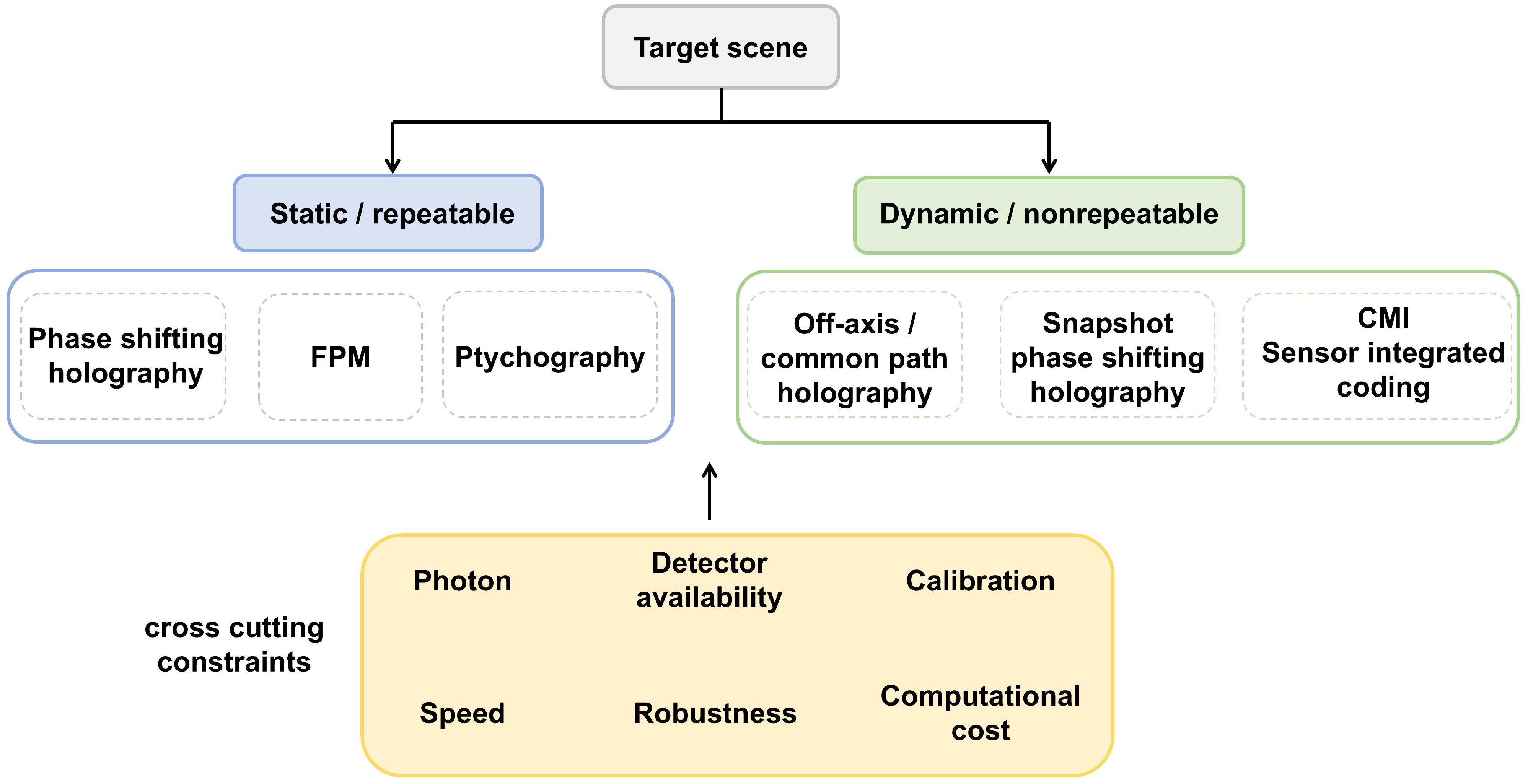
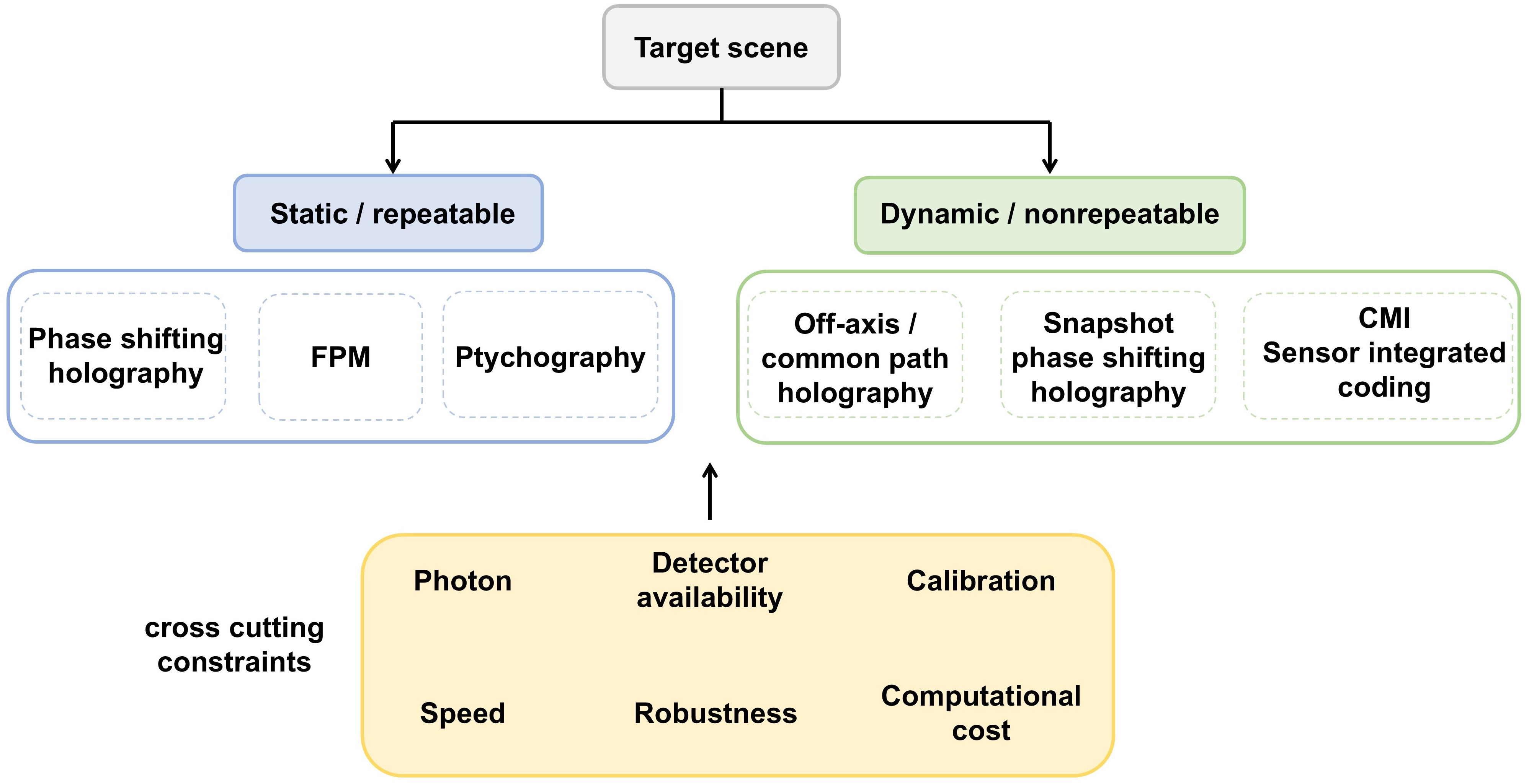
Figure 21. Application-oriented selection guide for modulation-enabled phase imaging. FPM: Fourier ptychographic microscopy; CMI: coherent modulation imaging.
Overall, sequential diversity is advantageous when redundancy, quantitative stability, and self-calibration are prioritized. Snapshot multiplexing is advantageous when temporal consistency is the dominant constraint, provided that its sampling and photon-sharing penalties are acceptable. Angular and scanning diversity support synthetic-aperture or high-resolution imaging, whereas static detection-side coding supports compact and sensor-integrated platforms. Across these classes, a defensible selection requires explicit reporting of measurement count, raw acquisition window, reconstructed-field rate, photon or dose budget, calibration overhead, and end-to-end reconstruction time.
6. Emerging Regimes and Research Roadmap
Several emerging regimes impose constraints that cut across the interferometric-diffractive classification. Photon-limited and low-dose measurements change the relevant noise model and penalize lossy or highly redundant modulation. Vectorial imaging expands the unknown from a scalar phase to a polarization-dependent matrix or tensor. Ultrafast and nonrepeatable events require the information needed for reconstruction to be encoded within one exposure or one excitation event. Terahertz, X-ray, and electron systems are further shaped by wavelength-specific limitations in sources, modulators, detectors, coherence, and dose. These regimes are considered here as operating conditions rather than additional modulation categories.
6.1 Photon-limited and low-dose imaging
Under photon-limited conditions, modulation must be evaluated by information gained per detected photon rather than by state count alone. Amplitude masks discard photons, and sequential measurements divide the available dose over multiple detector readouts. Phase modulation can preserve higher optical throughput, although finite diffraction efficiency and light outside the useful order must still be included in the photon budget. Interferometric detection can improve the detectability of a weak object field by mixing it with a stronger reference, but an excessively strong reference can saturate the detector and does not remove shot noise or reference-induced fluctuations. Therefore, the useful reference level is set by a balance among heterodyne gain, full-well capacity, read noise, and phase variance.
The reconstruction likelihood should also follow the measurement statistics. An unweighted least-squares loss is convenient at moderate counts, but it assigns inappropriate confidence when the data are dominated by Poisson fluctuations or contain many zero-count pixels. Poisson-likelihood or variance-stabilized objectives, together with calibrated dark counts and detector gain, provide a more defensible basis for low-count phase retrieval[135]. Low-dose electron ptychography illustrates why the optical and computational terms cannot be separated. Numerical simulations using non-convex Bayesian optimization predicted that the dose required for successful cryo-electron ptychographic reconstruction could be reduced by approximately two orders of magnitude relative to previous experiments[44], while fast direct electron detectors and defocused probes have enabled atomic-resolution recovery at reduced dose[46]. Cryogenic electron ptychography has recovered biological phase information at 5.7 e/Å2[45], and mixed-state reconstruction has shown that explicitly modeling partial coherence can improve dose efficiency and precision[47]. More recent work has explored data-adaptive scan placement[145] and physically motivated low-dimensional parameterizations, such as atomic-orbital-like object functions and aberration-function probe models[146].
These results do not imply that additional priors create information that was never measured. Strong regularization, learned priors, or constrained object models can suppress noise and reduce variance, but they can also bias weak structures toward the assumed distribution. Low-photon reconstruction should therefore report the incident and detected photon or electron counts, the number of modulation states, optical throughput, detector noise, regularization strength, and uncertainty or repeatability of the recovered phase. Pixelwise uncertainty estimates have already been demonstrated for learned phase imaging[48]; extending such reporting to model-based and jointly calibrated reconstruction would make low-count results more comparable and reduce the risk of treating prior-induced structure as measured detail.
6.2 Vectorial and polarization-resolved imaging
Polarization can play two fundamentally different roles in modulated phase imaging. In snapshot phase-shifting systems, polarization is a carrier that multiplexes several scalar phase states onto different detector channels. The recovered unknown remains a scalar complex field, and the main errors arise from finite extinction ratio, retardance error, interpolation, and channel registration. In vectorial imaging, by contrast, the unknown is polarization dependent. A nondepolarizing thin specimen is represented by a spatially varying 2 × 2 complex Jones matrix, whereas depolarizing or partially polarized samples require Stokes-Mueller or higher-order coherence descriptions. Recovering these quantities requires multiple independent input and analyzer states, and global phase, gain, and basis ambiguities must be controlled by calibration or physical constraints.
Vectorial ptychography established a forward model in which a Jones-matrix object acts on vector-valued probes before diffraction[49]. Experimental studies subsequently recovered retardance, diattenuation, optical-path difference, and fast-axis orientation[50], and joint probe–object estimation relaxed the assumption that the polarized probes, including their amplitudes, wavefronts, and polarization states, were perfectly known[147]. Polarization-sensitive Fourier ptychography extended this approach to large-area birefringence imaging[148], while vectorial Fourier ptychography recovered the full complex Jones matrix together with polarization-dependent aberrations[51]. Polarization-sensitive intensity diffraction tomography further generalized the problem to 3D anisotropy using a vectorial multislice propagation model[52]. These developments directly address the limitation that polarization multiplexing alone is not equivalent to recovering the vector polarization field or material anisotropy.
The remaining challenge is identifiability under realistic vectorial model mismatch. Polarizer and analyzer errors, spatially varying retardance, polarization-dependent pupil aberrations, high-NA vector diffraction, multiple scattering, and sample depolarization can all make a nominal Jones model incomplete. Increasing the number of polarization states improves redundancy but also increases acquisition time and divides the photon budget. Future systems should therefore co-design a minimal set of polarization, angular, and spatial modulation states with a forward model matched to the sample class. For thin nondepolarizing samples, Jones-matrix recovery may be sufficient; for thick or multiple-scattering but approximately nondepolarizing specimens, vectorial multislice Jones or dielectric-tensor models may be appropriate. Depolarizing specimens instead require Mueller- or coherency-matrix descriptions, together with uncertainty measures that indicate which tensor components are actually supported by the measurements.
6.3 Ultrafast and non-visible-wavelength imaging
Ultrafast imaging requires a distinction among exposure duration, inter-frame interval, modulation rate, and reconstruction latency. A method can use a femtosecond pulse yet remain slow if it scans many positions, and it can acquire one camera frame without uniquely encoding all object dimensions. Nonrepeatable dynamics impose the stronger requirement that the information needed for reconstruction be recorded within one excitation event. Single-shot X-ray holography with extended references demonstrated direct reconstruction with an integration time of 20 fs[149], while separated objects have been used as unknown references for single-shot phase retrieval[150]. Time-resolved imaging by multiplexed ptychography was proposed and numerically demonstrated to reconstruct 15 temporal frames from a single noisy camera snapshot; the experimental demonstration was limited to single pulse single-shot ptychography[151]. As an example of high-speed rather than single-event ultrafast imaging, programmable DMD illumination has enabled Fourier-ptychographic QPI at more than 42 frames per second under the reported sequential-acquisition conditions[144]. At free-electron-laser sources, orbital angular momentum (OAM) probes have been used in single-shot-per-position ptychography, improving resolution relative to Gaussian probes and providing a potential route toward time-resolved imaging[152].
The physical cost of snapshot acquisition is that spatial, spectral, polarization, or angular channels share a finite detector bandwidth and photon budget. A reliable ultrafast system must therefore demonstrate not only single-exposure operation, but also sufficient measurement rank, tolerance to pulse-to-pulse source variation, synchronization accuracy, and robustness to detector saturation. Reconstruction latency should be reported separately from the physical temporal resolution. Learned or strongly regularized inversion can accelerate processing, but the resulting temporal sequence remains trustworthy only when the multiplexed measurement uniquely constrains the encoded frames and when out-of-distribution dynamics are detected rather than silently mapped to familiar training examples.
At terahertz wavelengths, the limited availability, cost, or speed of focal-plane arrays makes coded single-pixel detection more competitive than in visible-light microscopy. Active metamaterial SLMs have enabled compressive terahertz imaging[153], and optically patterned silicon combined with a single-pixel detector has demonstrated 32 × 32-pixel imaging at 6 frames per second[154]. Nonlinear ghost imaging has provided hyperspectral terahertz microscopy with subwavelength capability[155]. Deep-learning-optimized diffractive layers, combined with a single-pixel spectroscopic detector, have enabled rapid hidden-defect sensing without sample scanning or conventional image formation[156]. These examples show that modulation in difficult spectral bands may be designed around detector availability and task-specific sensing rather than around a direct translation of visible-light camera architectures.
X-ray and electron imaging face a different balance. Short wavelengths offer high spatial resolution, but radiation damage, source coherence, detector dynamic range, scan stability, and accumulated dose constrain the number of useful measurements. Ptychography and CDI are attractive because they use diffraction information that conventional lenses may not collect or preserve, yet their redundancy is beneficial only when the additional measurements contribute more information than damage. Low-dose, mixed-state, adaptive-scan, and single-shot strategies should therefore be evaluated using a common dose-information framework rather than resolution alone. Across terahertz, X-ray, and electron regimes, the modulation element, detector, likelihood model, and calibration procedure must be treated as a coupled system.
6.4 Modality-specific bottlenecks and research roadmap
Interferometric and diffractive methods share the general problem of model mismatch, but their dominant failure modes remain distinct. Interferometric imaging is limited primarily by reference stability, phase-step error, spatial-carrier bandwidth, zero-order and conjugate leakage, self-reference contamination, polarization-channel mismatch, and detector nonlinearity. Common-path designs reduce environmental sensitivity but do not guarantee an uncontaminated reference. Diffractive imaging is limited primarily by nonconvex ambiguity, insufficient sampling or diversity, probe, mask, position, distance error, partial coherence, accumulated scan dose, and gauge freedoms in blind reconstruction. More measurements can improve self-calibration in both branches, but they can also increase motion sensitivity, dose, and computational cost.
Near-term progress should focus on four deliverable goals. First, experiments should report standardized acquisition definitions, including exposure number, raw acquisition time, end-to-end reconstruction time, detected photon or electron counts, and calibration overhead. Second, differentiable calibration and joint estimation should be accompanied by identifiability checks so that object structure is not exchanged with an unconstrained pupil, probe, or mask. Third, uncertainty-aware reconstruction should be incorporated into phase imaging, particularly for low-count and learned inversions[48]. Fourth, programmable phase-only modulators should be characterized using their measured complex modulation response, wavelength dependence, and temporal drift rather than nominal phase specifications alone[56]. Sensor-integrated coding elements should likewise be characterized for fabrication variability, code-sensor spacing, pixel response, and long-term stability[39,131,132].
The longer-term direction is optical-modulation-sensor-algorithm co-design, for which related studies in computational imaging provide useful precedents. Computational metasurface imaging has paired subwavelength optical coding with numerical reconstruction[157], while differentiable optimization has jointly designed nano-optic and reconstruction networks[158]. Plug-and-play and related physics-based frameworks offer a way to use learned priors while retaining an explicit data-consistency operator[159]. Recent metaoptic computational-imaging perspectives further frame the optical encoder as a physical preconditioner that should be optimized together with the inverse algorithm[160]. We therefore argue that modulation-enabled phase imaging should extend these co-design principles toward identifiability, photon efficiency, calibration robustness, and uncertainty-aware recovery.
Figure 22 summarizes this roadmap. Near-term systems should become more reproducible, self-calibrating, photon aware, and explicit about uncertainty. Longer-term systems should combine programmable illumination, integrated vectorial or spectral coding, high-dynamic-range detectors, and reconstruction models that update system parameters online. The most demanding goal is single-exposure recovery of high-dimensional fields, including 3D, multispectral, and vectorial complex fields from nonrepeatable events. Such recovery will require hardware that encodes genuinely independent information and algorithms that can distinguish unsupported structure from measured detail.
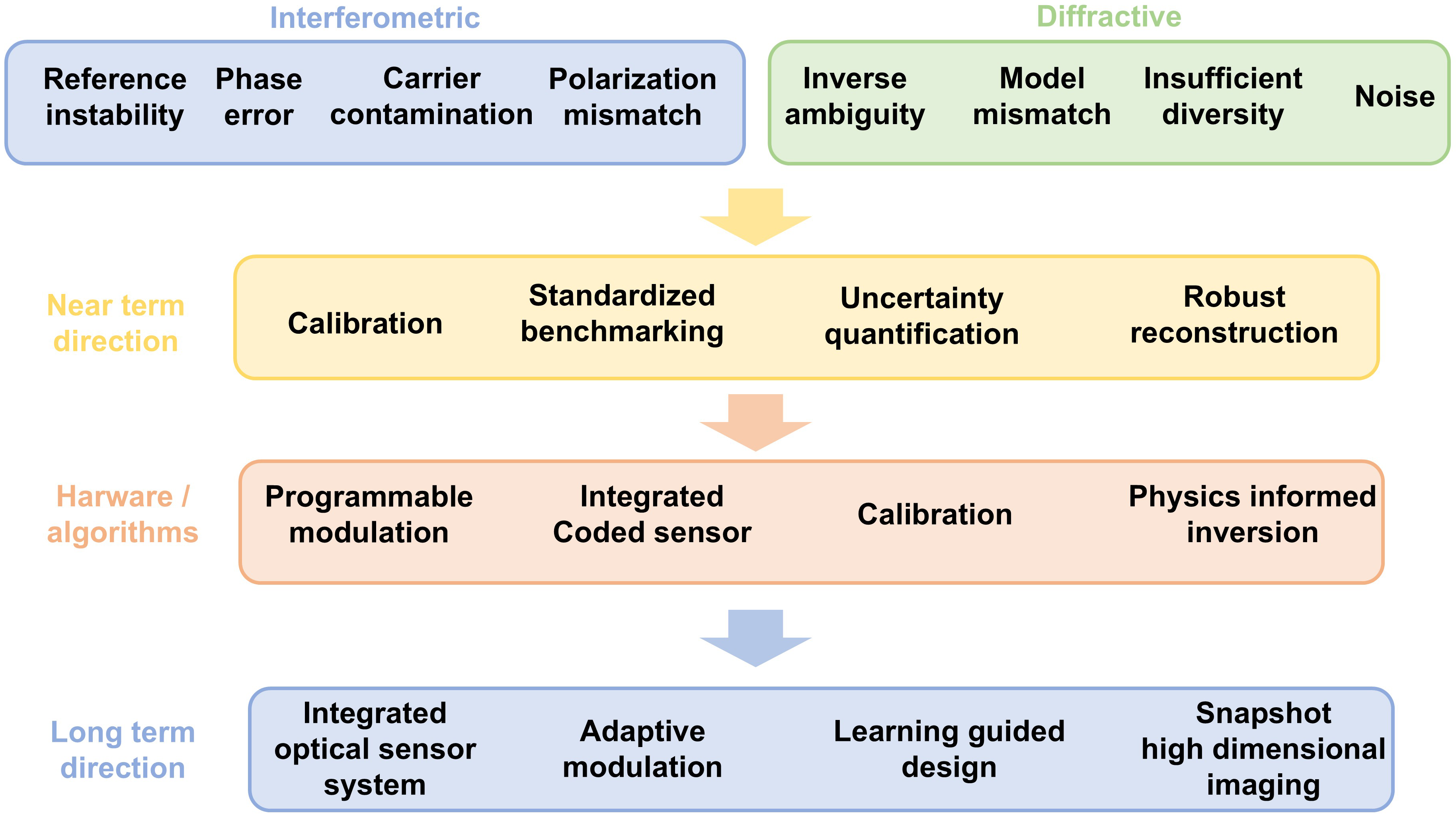
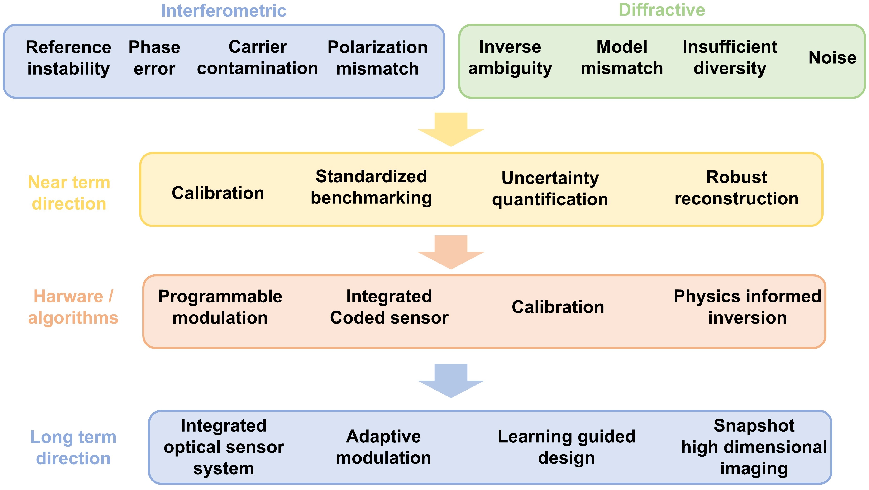
Figure 22. Branch-specific bottlenecks and research roadmap for modulation-enabled phase imaging. Near-term directions emphasize calibration, benchmarking, and uncertainty; long-term directions emphasize integrated and adaptive co-design for snapshot high-dimensional imaging.
The field should therefore move from adding modulation states to designing information-efficient measurement operators. Progress will be determined not only by higher nominal resolution or faster modulators, but by whether the complete system can recover phase and complex-field information with quantitatively validated accuracy and reported uncertainty under realistic photon, motion, calibration, and computational constraints.
7. Conclusion
Modulation-enabled phase imaging is best understood not as a collection of optical arrangements, but as the design of an information-bearing measurement operator. By locating modulation in the reference or interference path, illumination, propagation, or detection plane, this review provides a unified framework for relating optical encoding to phase observability, reconstruction conditioning, and model mismatch. This perspective clarifies the central contribution of modulation: it reshapes the forward model so that phase and, where supported, the full complex field can be inferred from intensity measurements. It also establishes a strict boundary. Reconstruction quality is ultimately limited by the information encoded in the measurements, the independence of the modulation states, detector sampling and noise, photon throughput, and the fidelity of the calibrated forward model.
Within this framework, the two branches create phase observability in distinct ways. In interferometric imaging, a reference field converts object phase into measurable intensity variations, enabling comparatively direct demodulation. Temporal phase shifting is therefore well suited to quantitative metrology when the specimen and interferometer remain stable across all required phase states. Single-exposure spatial-carrier implementations, including common-path off-axis schemes such as DPM, avoid sequential phase stepping but require adequate separation of the interference orders, careful Fourier filtering, and control of reference-wave curvature and spectral leakage. Snapshot spatial or polarization multiplexing further improves motion tolerance, but introduces channel-dependent sampling, crosstalk, retardance errors, and registration uncertainty. Accordingly, interferometric performance is governed chiefly by reference stability, phase-step or channel accuracy, detector bandwidth, self-reference contamination, and calibration of the complete interference model.
In contrast, diffractive methods recover phase through diversity in illumination, propagation, wavelength, scan position, speckle fields, or detection-side coding. This broader design space can support lensless operation, synthetic-aperture resolution, large space-bandwidth products, and imaging across terahertz, X-ray, and electron regimes. The associated measurement redundancy can also support joint estimation of the object and system quantities, including the probe, pupil, scan positions, coherence states, or coded mask. These capabilities shift the burden from reference stability to inverse-problem conditioning, computation, and calibration. They also introduce nonconvex ambiguities and sensitivity to probe, mask, position, and distance errors, while scanning or multi-state acquisition can increase acquisition time and accumulated dose. Taken together, these contrasting failure modes rule out a universal ranking of methods. Method selection should instead follow the dominant experimental constraint in each application. Sequential diversity generally provides stronger and better-separated constraints and may enable self-calibration when the joint inverse problem is identifiable, whereas snapshot encoding is better suited to dynamic or nonrepeatable samples. This temporal advantage comes at the cost of sharing finite detector bandwidth, spatial sampling, or photon budget among multiplexed channels.
Several emerging operating regimes sharpen these trade-offs rather than forming independent modulation categories. Photon-limited and low-dose imaging change the objective from maximizing the number of measurements to maximizing recoverable information per detected photon. Vectorial imaging expands the unknown from a scalar complex field to a matrix- or tensor-valued polarization response. Depending on the sample class, the polarization response may be represented by a Jones-matrix field propagated through a vectorial multislice model, by a dielectric-tensor description, or, for depolarizing samples or partially polarized fields, by a Mueller- or coherency-matrix description. Its recovery requires sufficiently independent polarization-sensitive states or channels. Ultrafast and nonrepeatable events require sufficient information to be encoded within one exposure or excitation event, whereas terahertz, X-ray, and electron systems are strongly constrained by wavelength-specific sources, modulators, detectors, coherence, and dose. Across these regimes, learning-based reconstruction can accelerate inversion, introduce useful priors, and compensate for certain systematic residual errors represented in the calibration or training data. However, it cannot make spatial frequencies or field components that were not physically encoded identifiable from the measurements. Its use should therefore remain coupled to data consistency, calibration, out-of-distribution testing, and uncertainty reporting.
The near-term priority is to make modulation-enabled imaging more reproducible and quantitatively comparable. This requires standardized reporting of exposure number, detected photon or electron counts, raw acquisition time, reconstructed-field rate, end-to-end latency, calibration overhead, and uncertainty; measured characterization of modulator and detector responses; and joint estimation of object and system parameters accompanied by identifiability analysis under realistic noise statistics. The longer-term direction is optical-modulation-sensor-algorithm co-design, in which programmable illumination, integrated coded sensors or metaoptics, adaptive acquisition, and physics-based learned priors are optimized together for information efficiency rather than image appearance alone. Although the interferometric and diffractive branches have different immediate bottlenecks, they share a long-term direction toward self-calibrating, photon-efficient, and uncertainty-aware recovery of 3D, multispectral, or vectorial complex fields, including those associated with dynamic or nonrepeatable events. Therefore, progress should be judged not only by nominal resolution or modulation speed, but by whether the complete system recovers physically supported phase and, where applicable, complex-field information with quantitatively validated accuracy and reported uncertainty under realistic photon, motion, calibration, and computational constraints.
Authors contribution
Hu S: Investigation, writing-original draft, visualization, writing-review & editing.
Li X: Writing-review & editing, supervision, funding acquisition.
He Y: Conceptualization, supervision, writing-review & editing.
Sun B: Supervision, writing-review & editing, funding acquisition.
Conflicts of interest
The authors declare no conflicts of interest.
Ethical approval
Not applicable.
Consent to participate
Not applicable.
Consent for publication
Not applicable.
Availability of data and materials
Not applicable.
Funding
This work was supported by the National Natural Science Foundation of China (62505161, 12274262), National Key Research and Development Program of China (2022YFC2807702), Natural Science Foundation of Shandong Province (ZR2023QF069, ZR2025MS952), and the Jinan government project (No.202228042).
Copyright
© The Author(s) 2026.
References
-
1. Park Y, Depeursinge C, Popescu G. Quantitative phase imaging in biomedicine. Nat Photonics. 2018;12(10):578-589.[DOI]
-
2. Miao J, Charalambous P, Kirz J, Sayre D. Extending the methodology of X-ray crystallography to allow imaging of micrometre-sized non-crystalline specimens. Nature. 1999;400(6742):342-344.[DOI]
-
3. Mir M, Wang Z, Shen Z, Bednarz M, Bashir R, Golding I, et al. Optical measurement of cycle-dependent cell growth. Proc Natl Acad Sci U S A. 2011;108(32):13124-13129.[DOI]
-
6. Kim MK. Phase microscopy and surface profilometry by digital holography. Light Adv Manuf. 2022;3(3):481-492.[DOI]
-
9. Jossou E, Assefa TA, Suzana AF, Wu L, Campbell C, Harder R, et al. Three-dimensional strain imaging of irradiated chromium using multi-reflection Bragg coherent diffraction. npj Mater Degrad. 2022;6:99.[DOI]
-
10. Lee D, Nam C, Kim J, Hwang S, Koo B, Hyun H, et al. Strain-associated nanoscale fluctuating lithium transport within single-crystalline LiNi1/3Mn1/3Co1/3O2 cathode particles. Nat Commun. 2025;16:9018.[DOI]
-
13. Shechtman Y, Eldar YC, Cohen O, Chapman HN, Miao J, Segev M. Phase retrieval with application to optical imaging: A contemporary overview. IEEE Signal Process Mag. 2015;32(3):87-109.[DOI]
-
16. Teague MR. Deterministic phase retrieval: A Green’s function solution. J Opt Soc Am. 1983;73(11):1434.[DOI]
-
17. Rodenburg JM. Ptychography and related diffractive imaging methods. In: Advances in imaging and electron physics. Amsterdam: Elsevier; 2008. p. 87-184.[DOI]
-
19. Zheng G, Horstmeyer R, Yang C. Wide-field, high-resolution Fourier ptychographic microscopy. Nat Photonics. 2013;7(9):739-745.[DOI]
-
21. Leith EN, Upatnieks J. Reconstructed wavefronts and communication theory. J Opt Soc Am. 1962;52(10):1123.[DOI]
-
25. Roy S, Parks D, Seu KA, Su R, Turner JJ, Chao W, et al. Lensless X-ray imaging in reflection geometry. Nat Photonics. 2011;5(4):243-245.[DOI]
-
27. Shu Y, Sun J, Lyu J, Fan Y, Zhou N, Ye R, et al. Adaptive optical quantitative phase imaging based on annular illumination Fourier ptychographic microscopy. PhotoniX. 2022;3(1):24.[DOI]
-
30. Wu X, Sun J, Chen Y, Wei J, Chen Q, Poon TC, et al. Wavelength-scanning pixel-super-resolved lens-free on-chip quantitative phase microscopy with a color image sensor. APL Photonics. 2024;9:016111.[DOI]
-
31. Lu X, Shao Y, Zhao C, Konijnenberg S, Zhu X, Tang Y, et al. Noniterative spatially partially coherent diffractive imaging using pinhole array mask. Adv Photon. 2019;1(1):016005.[DOI]
-
34. Chen Y, Ponomarenko SA, Cai Y. Experimental generation of optical coherence lattices. Appl Phys Lett. 2016;109(6):061107.[DOI]
-
36. Candès EJ, Li X, Soltanolkotabi M. Phase retrieval from coded diffraction patterns. Appl Comput Harmon Anal. 2015;39(2):277-299.[DOI]
-
39. Jiang S, Guo C, Song P, Zhou N, Bian Z, Zhu J, et al. Resolution-enhanced parallel coded ptychography for high-throughput optical imaging. ACS Photonics. 2021;8(11):3261-3271.[DOI]
-
40. Zheng G, Shen C, Jiang S, Song P, Yang C. Concept, implementations and applications of Fourier ptychography. Nat Rev Phys. 2021;3(3):207-223.[DOI]
-
41. Li M, Qin T, Gao Z, Bian L. Illumination schemes for coded coherent diffraction imaging: A comprehensive comparison. Opt Laser Technol. 2024;168:109861.[DOI]
-
42. Chaumet PC, Bon P, Maire G, Sentenac A, Baffou G. Quantitative phase microscopies: Accuracy comparison. Light Sci Appl. 2024;13:288.[DOI]
-
45. Zhou L, Song J, Kim JS, Pei X, Huang C, Boyce M, et al. Low-dose phase retrieval of biological specimens using cryo-electron ptychography. Nat Commun. 2020;11:2773.[DOI]
-
47. Chen Z, Odstrcil M, Jiang Y, Han Y, Chiu MH, Li LJ, et al. Mixed-state electron ptychography enables sub-angstrom resolution imaging with picometer precision at low dose. Nat Commun. 2020;11:2994.[DOI]
-
52. Song S, Kim J, Moon T, Seong B, Kim W, Yoo CH, et al. Polarization-sensitive intensity diffraction tomography. Light Sci Appl. 2023;12:124.[DOI]
-
53. Barty A, Boutet S, Bogan MJ, Hau-Riege S, Marchesini S, Sokolowski-Tinten K, et al. Ultrafast single-shot diffraction imaging of nanoscale dynamics. Nat Photonics. 2008;2(7):415-419.[DOI]
-
54. Hu BB, Nuss MC. Imaging with terahertz waves. Opt Lett. 1995;20(16):1716-1718.[DOI]
-
55. Bliokh KY, Karimi E, Padgett MJ, Alonso MA, Dennis MR, Dudley A, et al. Roadmap on structured waves. J Opt. 2023;25(10):103001.[DOI]
-
56. Yang Y, Forbes A, Cao L. A review of liquid crystal spatial light modulators: Devices and applications. Opto-Electron Sci. 2023;2(8):230026.[DOI]
-
57. Gabor D. A new microscopic principle. Nature. 1948;161(4098):777-778.[DOI]
-
59. Liu H, Vinu RV, Ren H, Du X, Chen Z, Pu J. Single-shot on-axis fizeau polarization phase-shifting digital holography for complex-valued dynamic object imaging. Photonics. 2022;9(3):126.[DOI]
-
60. Liu B, Fang X, Tian A, Wang S, Zhang R, Wang H, et al. Parallel phase-shifting digital holographic phase imaging of micro-optical elements with a polarization camera. Photonics. 2023;10(12):1291.[DOI]
-
64. Zhang Z, Wang T, Feng S, Yang Y, Lai C, Li X, et al. Sparse phase retrieval using a physics-informed neural network for Fourier ptychographic microscopy. Opt Lett. 2022;47(19):4909-4912.[DOI]
-
66. Arias Sosa YC, Vega GM, Valin Rivera JL, Lopes RM, Planos Valenzuela ME, Fernández MV, et al. Alternative use of reflection spatial light modulator in phase shifting digital Gabor holography. Optik. 2021;233:166609.[DOI]
-
70. Tahara T, Kanno T, Arai Y, Ozawa T. Single-shot phase-shifting incoherent digital holography. J Opt. 2017;19(6):065705.[DOI]
-
72. Takeda M, Ina H, Kobayashi S. Fourier-transform method of fringe-pattern analysis for computer-based topography and interferometry. J Opt Soc Am. 1982;72(1):156-160.[DOI]
-
79. Zheng J, Guo X, Ma Y, Wen K, An S, Wang X, et al. Structured illumination lensless digital holographic microscopy (SI-LDHM). Front Phys. 2024;12:1485687.[DOI]
-
85. Li F, Yan W, Tian P, Yang F, Peng F. Twin image reduction method for digital in-line holography by using a digital periphery. Optik. 2019;193:162988.[DOI]
-
88. Zuo C, Li J, Sun J, Fan Y, Zhang J, Lu L, et al. Transport of intensity equation: A tutorial. Opt Lasers Eng. 2020;135:106187.[DOI]
-
90. Gureyev TE, Nugent KA. Rapid quantitative phase imaging using the transport of intensity equation. Opt Commun. 1997;133(1-6):339-346.[DOI]
-
91. Xu C, Pang H, Cao A, Deng Q. Enhanced single-beam multiple-intensity phase retrieval using holographic illumination. Photonics. 2022;9(3):187.[DOI]
-
97. Chan WL, Charan K, Takhar D, Kelly KF, Baraniuk RG, Mittleman DM. A single-pixel terahertz imaging system based on compressed sensing. Appl Phys Lett. 2008;93(12):121105.[DOI]
-
99. Morris PA, Aspden RS, Bell JEC, Boyd RW, Padgett MJ. Imaging with a small number of photons. Nat Commun. 2015;6:5913.[DOI]
-
100. Edgar MP, Gibson GM, Padgett MJ. Principles and prospects for single-pixel imaging. Nat Photonics. 2019;13(1):13-20.[DOI]
-
101. Sinha A, Lee J, Li S, Barbastathis G. Lensless computational imaging through deep learning. Optica. 2017;4(9):1117-1125.[DOI]
-
103. Bai C, Peng T, Min J, Li R, Zhou Y, Yao B. Dual-wavelength in-line digital holography with untrained deep neural networks. Photon Res. 2021;9(12):2501-2510.[DOI]
-
106. Yu X, Zhao M, Wang S, Tian Z, Yang Y. TV-based phase retrieval for speckle coded diffraction imaging. Opt Lasers Eng. 2024;178:108210.[DOI]
-
107. He Y, Guo Y, Hu J, Li X, Ma Y, Sun B. Single-pixel coherent diffractive imaging based on super-pixel holography. J Opt. 2022;24(11):115604.[DOI]
-
108. Li M, Bian L, Zhang J. Multi-slice coded coherent diffraction imaging. Opt Lasers Eng. 2022;151:106929.[DOI]
-
110. Rodenburg JM, Faulkner HML. A phase retrieval algorithm for shifting illumination. Appl Phys Lett. 2004;85(20):4795-4797.[DOI]
-
111. Maiden A, Johnson D, Peng L. Further improvements to the ptychographical iterative engine. Optica. 2017;4(7):736.[DOI]
-
112. Shenfield A, Rodenburg JM. Evolutionary determination of experimental parameters for ptychographical imaging. J Appl Phys. 2011;109(12):124510.[DOI]
-
117. Zuo C, Sun J, Li J, Asundi A, Chen Q. Wide-field high-resolution 3D microscopy with Fourier ptychographic diffraction tomography. Opt Lasers Eng. 2020;128:106003.[DOI]
-
123. Muneta H, Horisaki R, Nishizaki Y, Naruse M, Tanida J. Single-shot blind deconvolution in coherent diffraction imaging with coded aperture. Opt Rev. 2023;30(5):509-515.[DOI]
-
124. Zhang F, Pedrini G, Osten W. Phase retrieval of arbitrary complex-valued fields through aperture-plane modulation. Phys Rev A. 2007;75(4):043805.[DOI]
-
125. Johnson I, Jefimovs K, Bunk O, David C, Dierolf M, Gray J, et al. Coherent diffractive imaging using phase front modifications. Phys Rev Lett. 2008;100(15):155503.[DOI]
-
126. Seaberg MH, d’Aspremont A, Turner JJ. Coherent diffractive imaging using randomly coded masks. Appl Phys Lett. 2015;107(23):231103.[DOI]
-
127. Chapman HN, Barty A, Bogan MJ, Boutet S, Frank M, Hau-Riege SP, et al. Femtosecond diffractive imaging with a soft-X-ray free-electron laser. Nat Phys. 2006;2(12):839-843.[DOI]
-
128. Zhao J, Xu W, Yi J, Wang B, Zhang F. Extended coherent modulation imaging for single-shot object retrieval free from illumination artifacts. Ultramicroscopy. 2022;240:113591.[DOI]
-
132. Jiang S, Guo C, Bian Z, Wang R, Zhu J, Song P, et al. Ptychographic sensor for large-scale lensless microbial monitoring with high spatiotemporal resolution. Biosens Bioelectron. 2022;196:113699.[DOI]
-
133. Gerchberg RW, Saxton WO. A practical algorithm for the determination of phase from image and diffraction plane pictures. Optik. 1972;35(2):237-246. Available from: https://cir.nii.ac.jp/crid/1572543025237483520
-
135. Thibault P, Guizar-Sicairos M. Maximum-likelihood refinement for coherent diffractive imaging. New J Phys. 2012;14(6):063004.[DOI]
-
138. Cherukara MJ, Zhou T, Nashed Y, Enfedaque P, Hexemer A, Harder RJ, et al. AI-enabled high-resolution scanning coherent diffraction imaging. Appl Phys Lett. 2020;117(4):044103.[DOI]
-
140. Hoidn O, Mishra AA, Mehta A. Physics constrained unsupervised deep learning for rapid, high resolution scanning coherent diffraction reconstruction. Sci Rep. 2023;13:22789.[DOI]
-
141. Metzler CA, Schniter P, Veeraraghavan A, Baraniuk RG. prDeep: Robust phase retrieval with a flexible deep network. In: Proceedings of the 35th International Conference on Machine Learning; 2018 Jul 10-15; Stockholm, Sweden. International Machine Learning Society (IMLS); 2018;8:5654-5663. Available from: https://proceedings.mlr.press/v80/metzler18a/metzler18a.pdf
-
143. Bostan E, Heckel R, Chen M, Kellman M, Waller L. Deep phase decoder: Self-calibrating phase microscopy with an untrained deep neural network. Optica. 2020;7(6):559-562.[DOI]
-
148. Song S, Kim J, Hur S, Song J, Joo C. Large-area, high-resolution birefringence imaging with polarization-sensitive Fourier ptychographic microscopy. ACS Photonics. 2021;8(1):158-165.[DOI]
-
151. Sidorenko P, Lahav O, Cohen O. Ptychographic ultrahigh-speed imaging. Opt Express. 2017;25(10):10997-11008.[DOI]
-
152. Pancaldi M, Guzzi F, Bevis CS, Manfredda M, Barolak J, Bonetti S, et al. High-resolution ptychographic imaging at a seeded free-electron laser source using OAM beams. Optica. 2024;11(3):403-411.[DOI]
-
153. Watts CM, Shrekenhamer D, Montoya J, Lipworth G, Hunt J, Sleasman T, et al. Terahertz compressive imaging with metamaterial spatial light modulators. Nat Photonics. 2014;8(8):605-609.[DOI]
-
155. Olivieri L, Gongora JST, Peters L, Cecconi V, Cutrona A, Tunesi J, et al. Hyperspectral terahertz microscopy via nonlinear ghost imaging. Optica. 2020;7(2):186.[DOI]
-
156. Li J, Li X, Yardimci NT, Hu J, Li Y, Chen J, et al. Rapid sensing of hidden objects and defects using a single-pixel diffractive terahertz sensor. Nat Commun. 2023;14:6791.[DOI]
-
158. Tseng E, Colburn S, Whitehead J, Huang L, Baek SH, Majumdar A, et al. Neural nano-optics for high-quality thin lens imaging. Nat Commun. 2021;12:6493.[DOI]
-
159. Kamilov US, Bouman CA, Buzzard GT, Wohlberg B. Plug-and-play methods for integrating physical and learned models in computational imaging: Theory, algorithms, and applications. IEEE Signal Process Mag. 2023;40(1):85-97.[DOI]
-
160. Roques-Carmes C, Wang K, Yang Y, Majumdar A, Lin Z. Metaoptic computational imaging. ACS Photonics. 2025;12(4):1722-1733.[DOI]
Copyright
© The Author(s) 2026. This is an Open Access article licensed under a Creative Commons Attribution 4.0 International License (https://creativecommons.org/licenses/by/4.0/), which permits unrestricted use, sharing, adaptation, distribution and reproduction in any medium or format, for any purpose, even commercially, as long as you give appropriate credit to the original author(s) and the source, provide a link to the Creative Commons license, and indicate if changes were made.
Publisher’s Note
Science Exploration remains a neutral stance on jurisdictional claims in published
maps
and institutional affiliations. The views expressed in this article are solely those
of
the author(s) and do not reflect the opinions of the Editors or the publisher.
Share And Cite


Science Exploration Style
Hu S, Li X, He Y, Sun B. Optical field modulation for phase imaging: A unified framework for interferometric and diffractive strategies. Light Manip Appl. 2026;1:202614. https://doi.org/10.70401/lma.2026.0018
Tips
Copy completed.
Submit a Manuscript
Author Instructions
Cite this Article
Article Metrics
0
View
0
Download
Cited
Article Updates

- Abstract
- Keywords
- 1. Introduction
- 2. Theoretical Framework for Modulation-Enabled Phase Imaging
- 3. Optical-Field Modulation in Interferometric Phase Imaging
- 4. Optical-Field Modulation in Diffractive Phase Imaging
- 5. Cross-Strategy Comparison and Method Selection
- 6. Emerging Regimes and Research Roadmap
- 7. Conclusion
- Authors contribution
- Conflicts of interest
- Ethical approval
- Consent to participate
- Consent for publication
- Availability of data and materials
- Funding
- References
- Copyright
 Get citation
Science Exploration Style

Hu S, Li X, He Y, Sun B. Optical field modulation for phase imaging: A unified framework for interferometric and diffractive strategies. Light Manip Appl. 2026;1:202614. https://doi.org/10.70401/lma.2026.0018
copy
Share Link
copy