Enhancing the shear properties of U-Shaped steel wire mesh reinforced 3D printed composites
*Correspondence to:
Miao Liu, Karara Mining Limited, Level 2, London House, 216 St George’s Terrace, Perth WA 6000, Australia.
E-mail: miao.liu@kararamining.com.au
J Build Des Environ. 2025;3:202567. 10.70401/jbde.2025.0020
Received: August 25, 2025Accepted: December 05, 2025Published: December 16, 2025
This article belongs to the Special lssue Advances in Construction Materials, Structures and Geotechnical Engineering
Abstract
3D-printed concrete (3DPC) represents a rapidly developing technology with numerous applications in construction. The properties of 3DPC under both static and dynamic loads can be enhanced by incorporating reinforcement. This study presents a novel reinforcement technique utilizing U-shaped steel wire mesh (U-shape SWM). This technique involves integrating both horizontal and vertical reinforcements during the concrete printing process. Additionally, a new fabrication process was developed using a dual-arm robotic system, with each arm equipped with shaping and welding tools, to autonomously create U-shape SWM structures. An experimental investigation was conducted on specimens reinforced with either flat or U-shape SWM reinforcements under flexural loading. Compared to the specimens reinforced with a single layer of 6-mm flat SWM under a shear-span ratio of 2, those incorporating one layer of U-shape SWM combined with two layers of 6-mm flat mesh exhibited a 200% increase in failure load and a 26.09% increase in cracking load, while the ultimate displacement decreased by approximately 6%. Under a reduced shear-span ratio of 0.5, this reinforcement configuration reached a failure load of 43.6 kN, a cracking load of 16.1 kN, and an ultimate displacement of 11.1 mm. Furthermore, an analytical model based on the strut-tie model was developed to predict the load-bearing capacity of the reinforced specimens. The model predictions showed good correspondence with the experimental results.
Keywords
U-shape steel wire mesh, 3D-printed concrete, shaping and welding robotic arms, analytical model
1. Introduction
3D-printed concrete (3DPC) is a prospective technique for accelerating construction and automation. Its application can significantly reduce construction costs, time, and the need for formworks[1-4]. As industrial interest in the technology grows, research efforts have increasingly focused on its various aspects to expand its practical applicability, such as mixture design[5-8], rheology and early-age behavior[9-12], and long-term mechanical properties[13-16].
Introducing reinforcement into printed concrete can improve its mechanical performance and broaden its applicability in structural engineering. Among various reinforcement strategies, fiber addition has been widely adopted to improve the properties of 3DPC structures[17,18]. Hambach and Volkmer[19] reported that fibers aligned with the printed direction greatly increased the flexural strength to 30 MPa compared to that unreinforced counterparts. Arunothayan et al.[20] tested printable ultra-high-performance concrete (UHPC) containing short steel fibers orientated parallel to the printing direction. They concluded that the printed UHPC samples exhibited better property than those of the mold-cast UHPC. Furthermore, Bos et al.[21] found that short, straight steel fibers enhanced the flexural strength and ductility in printed structures.
In studies on steel coil-reinforced 3D-printed concrete, Khoshnevis[22] expand the functionality of printed concrete by replacing steel coil fibers with entrained cables. The reinforcing effect of steel cables on the flexure property of printed concrete has been investigated using varying cable strengths[23] and diameters[24]. Besides, Li et al.[25] examined cable distributions in printed geopolymer and observed improvements in post-peak behavior, fracture toughness, and ductility compared with unreinforced specimens.
Perrot et al.[26] used nail insertions in freshly extruded layers to align fibers across the printed concrete, enhancing flexural strength. Similarly, Geneidy et al.[27] integrated an electrical staple gun into the printing system to automate fiber reinforcement; however, this method generated little improvement in flexural strength. Moreover, Hass and Bos[28] presented a vertical screw reinforcement technique and evaluated its effect on printed concrete through pull-out and flexure examinations.
Marchment and Sanjayan[29] designed a device to automatically insert steel wire mesh (SWM) to reinforce the layer during printing. The SWM with two layers of height was inserted into the printing layer to provide continuous internal reinforcement of components. Norman et al.[30] verified the feasibility of the device in manufacturing the double-curved wall.
Asprone et al.[31] utilized an external reinforcement system to connect printed segments and anchored steel rebars at predefined locations. This method’s feasibility was proved through flexural tests on assembled beams. Ghent University has combined 3DPC with topology optimization to manufacture assembly girder, subsequently reinforced by post-tensioning[32]. Similarly, Eindhoven University of Technology constructed a bicycle bridge integrating 3DPC and prestressing technologies, which was opened to the public after scaled models and field tests[33,34]. Existing reinforcement methods in the literature (such as fibers, cables, and traditional planar meshes) improved the performance of 3DPC. However, current research still lacks technical solutions for simultaneously incorporating longitudinal and transverse U-shape steel wire mesh (U-shape SWM) reinforcement during the 3D printing process. Fiber reinforcement enhances tensile properties and crack resistance along the printing path but has limited interlayer bonding and shear transfer[35,36]. Cable or nail insertion techniques can improve local flexural performance, but face challenges in automation and positional precision. Furthermore, the robotic manufacturing process integrates shaping, welding, and printing within a single automated system, offering improved precision and construction efficiency relative to conventional reinforcement strategies. This integration of mechanical enhancement and automation readiness positions the U-shape SWM as a promising approach for next-generation 3DPC structures. Therefore, this research intends to explore innovative techniques for the automated fabrication of prefabricated U-shaped single-wall panels using 3DPC, as well as their integration into printed concrete.
An in-process reinforcing approach for 3DPC, along with the necessary instrumentation, has been developed to advance construction automation. This method has been validated to provide continuous U-shape SWM reinforcement in lab-scale printing. Besides, the effectiveness of U-shape SWM was demonstrated through four-point flexure tests.
2. Concept of U-shape SWM Manufacturing
This section introduces a robotic system equipped with the necessary shaping and welding tools to autonomously fabricate U-shape SWM structures in laboratory settings. Section 2.1 reviews the background and motivation of the system, while Section 2.2 details the hardware design of the robot end effectors used for shaping and welding.
2.1 Overview of U-shape SWM manufacturing technology
A versatile robotic platform was developed for the fabrication of U-shape SWM, as depicted in Figure 1. This platform features a robust design with two robotic arms mounted on a cast iron base, ensuring stability throughout the printing process. The design incorporates overlapping workspaces between the two arms, defining the fabrication zone. To accommodate the complex and flexible requirements of integrating U-shape SWM into 3D concrete printing, the robotic system is equipped with high-precision, custom-designed end effectors. Its flexibility is enhanced by its ability to rapidly interchange different end effectors. The first end effector is specialized for U-shape SWM fabrication, incorporating mechanisms for conveying and straightening horizontal and vertical steel wires. The second end effector functions as a cut-off and welding device, facilitating the precise fabrication of U-shape SWM. The third end effector is designed for concrete printing, featuring a print nozzle that can be mounted on the robotic arm. During the printing process, the third end effector replaces the second, allowing seamless transitions between U-shape SWM fabrication and concrete printing.
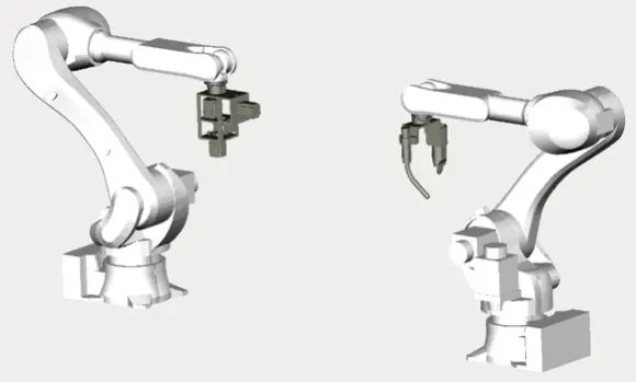
Figure 1. Concept of 6-axis robot arms for U-shape SWM production. U-shape SWM: U-shaped steel wire mesh.
The free-form U-shape SWM is adaptable to the dimensions of the printed structure. Production feedback generated during the U-shape SWM fabrication is automatically relayed to the control software, which then recalibrates the robot arms to ensure precise adjustments. The appropriate end effector is employed for the flexible forming of the steel wire, while another robot arm performs the welding at the mesh nodes. This integration of automated feedback with precise robotic control boosts the accurate production of U-shape SWM tailored to the specific demands of 3D-pinted concrete.
2.2 End-effector of the robot arm
As previously discussed, the system employs two distinct mechanical end effectors, each responsible for a specific function: (i) aligning and transporting the steel wire, and (ii) performing cutting and welding operations at designated positions. Function (i) is accomplished through an independent design tool that shapes the steel wires into the U-shape SWM configuration (Figure 2a). Function (ii) is carried out using pneumatic scissors and a spot-welding device, which together enable precise cutting and welding operations as required (Figure 2b). This dual-function approach integrates seamlessly with the 3D-pinted concrete, enhancing both the adaptability and accuracy of U-shape SWM production.
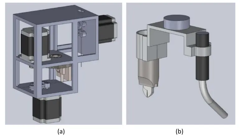
Figure 2. End effectors: (a) wire straightening, conveying, and shaping end effector; (b) Wire cutting and welding end effector.
The end effector serves as the primary sub-system to perform wire forming tasks (Figure 2a). The conveying mechanism operates through a motorized conveyor running at a constant speed regulated by a closed loop feedback. The conveyor module, situated along the bottom and side of the end effector platform, comprises left- and right-conveying wheels with mirror image. One wheel is driven by a servo motor, while the other is adjustable to modify both the conveying force and the steel wire diameter. Positioned upstream of the conveyor, the straightening mechanism uses a straightening roller to accommodate wires of different diameters. Additionally, the shaping mechanism enables the formation of diverse wire geometries through precise servo-controlled rotations.
The cut-off and welding end effector, illustrated in Figure 2b, integrates pneumatic shears with a welding torch mounted on the side of the Y-shaped frame. Its function is switched by rotating the robot arm’s wrist: rotating outward positions the pneumatic scissors for cutting, while rotating the welding gun outward activates the welding mode. The robot arm’s micrometer-level positional accuracy ensures the precise execution of both cutting and welding tasks, meeting the stringent requirements of 3D concrete printing.
3. Materials and Methods
The section introduces the materials used for preparing printed concrete composites and the experimental program conducted on the printed specimens, including the design and fabrication of test specimens, and test setup and instrumentation.
3.1 Materials
Silica fume and Ordinary Portland cement PO 42.5 were used as binder materials. Silica sand with particle sizes ranging from 0.02 to 1 mm, served as the aggregate. A naphthalene-based high-range water reducer (HRWR) was incorporated to improve the rheological properties of the mixture. The mixture was prepared by blending the materials with water at a 0.28 water-to-binder ratio. The mass-based mixing ratios are summarized in Table 1. The mix design was developed based on prior studies on printable cementitious materials and further optimized through rheological and printability tests. The resulting mixture exhibited a well-balanced combination of extrudability, buildability, and interlayer adhesion, with a static yield stress of approximately 1.5 kPa and a plastic viscosity of around 50 Pa·s. Multiple trial prints were conducted to verify that the mixture could be continuously extruded and stacked without deformation or collapse.
Table 1. Mix proportions for printing (kg/m3).
| Cement | Water | Silica sand | Silica fume | HRWR |
| 798.47 | 279.47 | 998.09 | 191.63 | 4.12 |
HRWR: high-range water reducer.
This process of material mixing was conducted in a 50-liter capacity mixer. Initially, the dry components—cement, silica fume, and silica sand—were combined and mixed for 1 minute. Subsequently, half of the HRWR and water were added, followed by another 1 minute of mixing. The remaining HRWR and water were then introduced and mixing continued for 3 minutes to ensure the mixture’s homogeneity.
The SWM, utilized as reinforcement, was manufactured from 304 stainless steel. The mesh comprised orthogonally arranged steel wires welded at their intersections, with wire diameters of 1 mm and mesh sizes of 6 mm, 8 mm, and 12 mm, as depicted in Figure 3. Before being incorporated into the 3D printed concrete, the SWM was bent into a U shape using a bending machine to enhance shear resistance in the reinforced specimens.
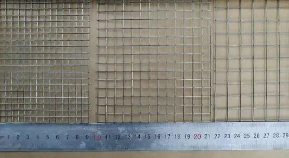
Figure 3. The SWM used for reinforcement with different mesh sizes. SWM: steel wire mesh.
3.2 samples design and preparation
All printed specimens were fabricated with uniform external dimensions of 400 mm × 100 mm × 100 mm (GB/T 50081-2019). Each configuration was printed and tested in triplicate (n = 3) to ensure reproducibility. The experimental specimens are labeled as M#U#F#λ#, where the digit following each letter signifies a specific characteristic: M indicates the size of the U-shape SWM in millimeters; U denotes the number of U-shape SWM layers; F represents the quantity of flat SWM layers (those not shaped into U), and λ corresponds to the shear-span ratio. As an example, M6U1F2λ2 refers to a sample with a 6 mm grid size, one layer of U-shape SWM, two layers of flat SWM, and a shear span ratio of 2. The experimental samples include both specimens reinforced with both flat and U-shape SWM, with variations in the vertical grid size of the U-shape SWM. A summary of the specimen configurations is presented in Table 2, indicating that the overall dimensions of the reinforced SWM remained consistent, except for differences in mesh size.
Table 2. Sample configurations.
| Specimen Designation | Shear Span Ratio | The Wire’s Diameter (mm) | Grid Scale(mm) | Steel Wire Mesh Shape |
| M6U0F1λ2 | 2 | 1 | 6 | 1 flat |
| M6U1F0λ2 | 2 | 1 | 6 | 1 U-shape |
| M6U0F3λ2 | 2 | 1 | 6 | 3 flat |
| M6U1F2λ2 | 2 | 1 | 6 | 1 U-shape + 2 flat |
| M6U1F2λ1 | 1 | 1 | 6 | 1 U-shape + 2 flat |
| M6U1F2λ0.5 | 0.5 | 1 | 6 | 1 U-shape + 2 flat |
| M8U1F2λ1 | 1 | 1 | 8 | 1 U-shape + 2 flat |
| M8U1F2λ1.5 | 1.5 | 1 | 8 | 1 U-shape + 2 flat |
| M12U1F2λ2 | 2 | 1 | 12 | 1 U-shape + 2 flat |
| M12U1F2λ1 | 1 | 1 | 12 | 1 U-shape + 2 flat |
| M12U1F2λ1.5 | 1.5 | 1 | 12 | 1 U-shape + 2 flat |
In 3D-pinted concrete, the extruder axis is typically oriented vertically. However, when using U-shape SWM reinforcement, a vertical extruder axis may collide with the vertical sections of the pre-arranged U-shape SWM, as shown in Figure 4a. To avoid such collisions, the nozzle axis can be tilted to align with the tangential vector of the perpendicular sections of the U-shape SWM. This adjustment is achieved using a six-axis robotic printer, allowing the nozzle to tilt relative to the tangent vector at the extrusion location, as illustrated in Figure 4b. Figure 4c demonstrates the designed print path that prevents nozzle collisions with the U-shape SWM. The nozzle, positioned at location A in Figure 4b, prints along path 1 while tilting to avoid the vertical SWM. After traversing the vertical segment at the end of path 1, printing continues along subsequent paths, with the nozzle maintaining its designated tilt angle. It should be noted that the tilt angle of the nozzle may vary to accommodate different print paths within the same layer. For the example in Figure 4, the nozzle tilts to position A to print path 1, tilts to position B for paths 2-4, tilts to position C for paths 5-7, and finally tilts to position D for path 8.
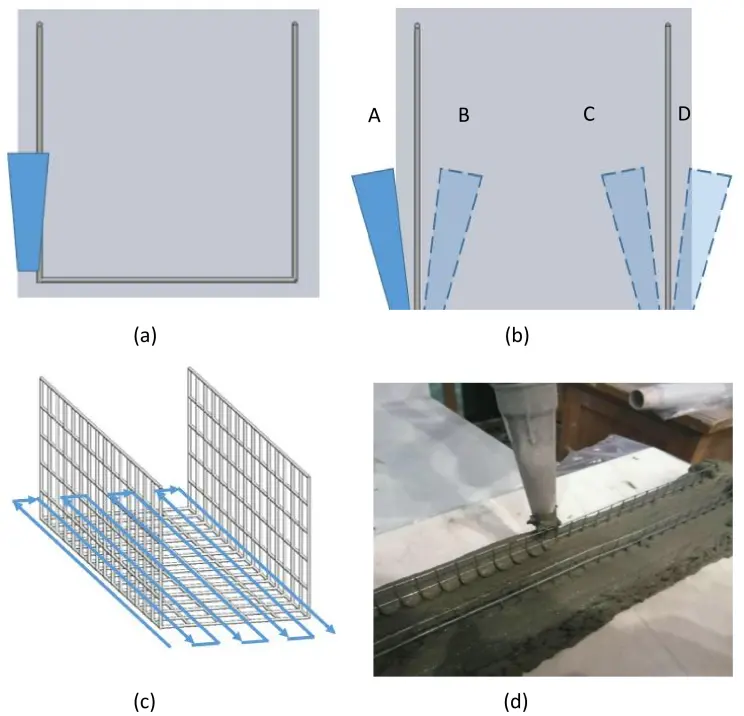
Figure 4. (a) Nozzle colliding with vertical SWM; (b) The ideal inclination angle of the nozzle; (c) The ideal printing path free from collisions; (d) U-shape SWM reinforced samples in print process. U-shape SWM: U-shaped steel wire mesh.
All specimens were fabricated using a six-axis robotic concrete printer equipped with a 20 mm nozzle. The printing was performed at a speed of 100 mm/s, with a layer height of 10 mm and an interlayer interval of 5 minutes, to ensure proper adhesion between layers while preventing deformation of the lower layers. The nozzle inclination angle was automatically adjusted between 0° and 20° to avoid interference with the U-shaped reinforcement. All printing was conducted in a controlled environment at 23 ± 2 °C and 50 ± 5 % RH. Prior to printing, the U-shape SWM reinforcement was positioned on the print panel, and the printing path was performed without squeezing the concrete to verify that no collisions would occur between the nozzle and the U-shape SWM. Print proceeded only if no collisions were detected. The fabrication process began with printing a cover layer to encapsulate the reinforcement. Subsequently, the U-shape SWM was placed on this initial printed layer. Then continue printing the second layer using the inclined nozzle mounted on the robot arm. After each printed layer, a flat SWM reinforcement layer was inserted between the vertical sections of the U-shape SWM. This procedure was repeated until the desired number of flat SWM layers was achieved, followed by a top cover layer to complete the specimen. As illustrated in Figure 4d, the concrete fully surrounds the vertical mesh, ensuring good contact with the U-shape SWM. A limitation of this fabrication technology is that the printable concrete cannot contain aggregates larger than the grid size. After printing, the specimens were wrapped in a plastic container and permitted to cure at ambient temperature for 24 hours to prevent shrinkage. They were then transferred to a standard curing room (20 ± 2 °C, 95% RH) for an additional 28 days. To prepare for digital image correlation, the specimens’ surfaces were smoothed using a polishing machine and speckled with aerosol paint one day before testing.
3.3 Test setup and instrumentation
The performance of the reinforced specimens was evaluated by four-point bending experiments. These experiments were conducted on an MTS 793 hydraulic universal testing machine with a load capacity of 1500 kN, as described in Figure 5. The distance between the two supports was maintained at 300 mm. A uniaxial load was monotonically applied to the specimen in displacement control mode at a constant rate (1 mm/min).
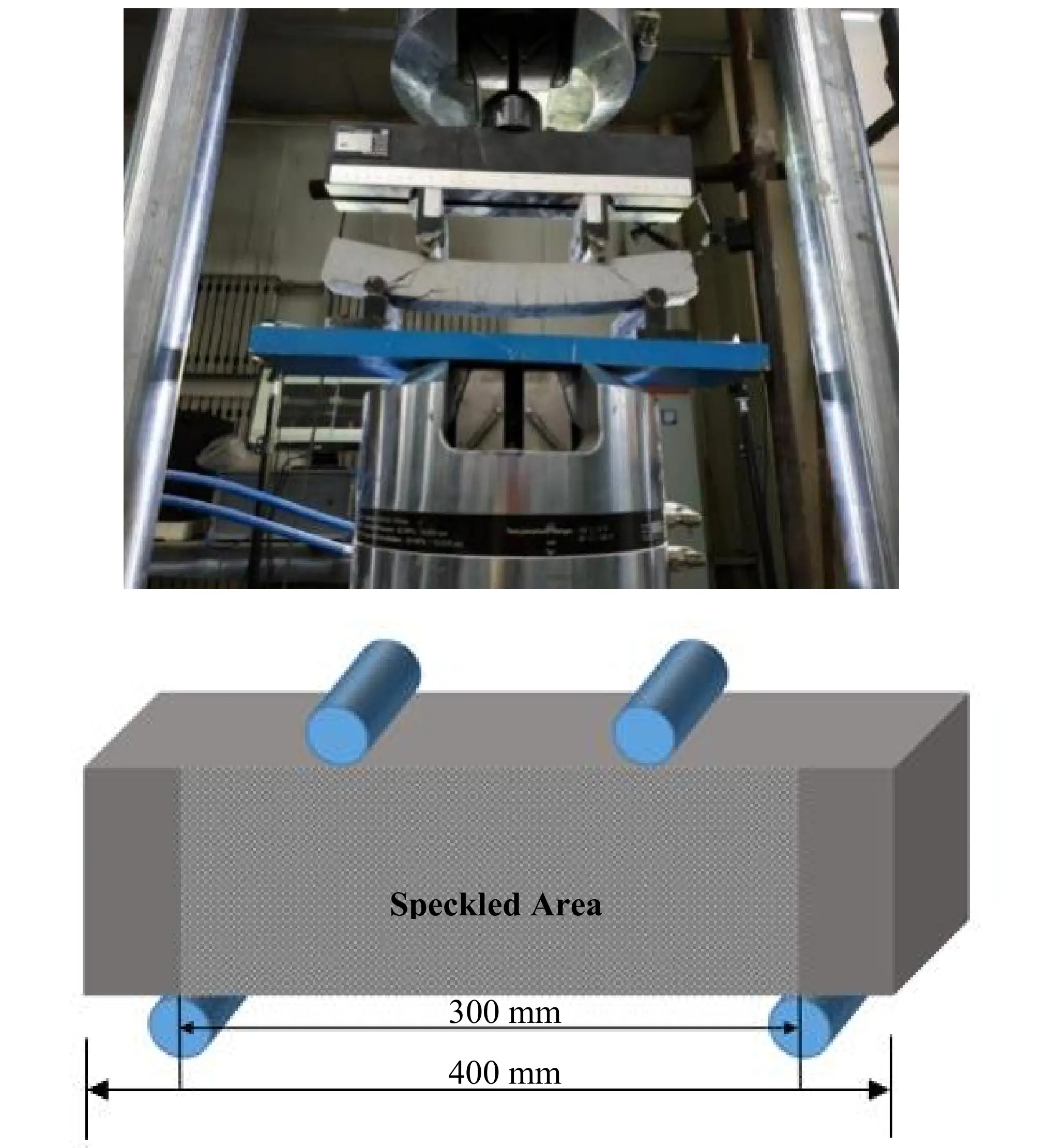
Digital imaging correlation (DIC) technology was employed to delineate deformation under loading. Before testing, the specimens’ surfaces were polished and speckled with aerosol paint one day to facilitate digital imaging. Two charge-coupled device cameras recorded images of the speckled area during the tests, which were subsequently processed using DIC to evaluate the displacement and strain fields at any loading stage. High-intensity flashlights were employed to ensure uniform illumination of the specimens, and the imaging setup was calibrated for synchronization before testing. The image acquisition frequency for the DIC test was set at 0.15Hz. The loading mode of the universal testing machine was configured as displacement control, with a reduced rate of 0.2 mm/min to capture material deformation under the applied load. The images were captured using VIC-3D software by Correlated Solutions, Inc.
4. Results and Discussions
The experimental results include the cracking loading, failure loading, mid-span displacement at failure, and failure patterns of the 3D-printed samples reinforced with U-shape SWM (Table 3). Overall, the results demonstrate that the U-shape SWM reinforcement system effectively enhances the load-carrying capacity of the printed composites.
Table 3. experiment results of printing samples with U-shape SWM reinforcement.
| Specimen Designation | Failure Loading (kN) | Cracking Loading (kN) | Failure pattern | Displacement at Ultimate Load (mm) |
| M6U0F1λ2 | 3.3 ± 0.2 | 2.3 ± 0.1 | Flexure | 16.2 ± 0.9 |
| M6U1F0λ2 | 7.2 ± 0.3 | 2.8 ± 0.1 | Flexure | 30.3 ± 1.2 |
| M6U0F3λ2 | 7.8 ± 0.4 | 3.1 ± 0.2 | Flexure + Shear | 24.2 ± 1.0 |
| M6U1F2λ2 | 9.9 ± 0.5 | 2.9 ± 0.2 | Flexure + Crush | 15.2 ± 0.8 |
| M6U1F2λ1 | 26.2 ± 1.1 | 6.3 ± 0.3 | Shear | 15.6 ± 0.7 |
| M6U1F2λ0.5 | 43.6 ± 1.8 | 16.1 ± 0.7 | Shear | 11.1 ± 0.6 |
| M8U1F2λ1 | 28.6 ± 1.2 | 6.0 ± 0.3 | Flexure + Crush | 8.1 ± 0.4 |
| M8U1F2λ1.5 | 14.9 ± 0.7 | 2.9 ± 0.1 | Flexure + Crush | 12.6 ± 0.5 |
| M12U1F2λ2 | 5.4 ± 0.2 | 2.7 ± 0.1 | Flexure + Crush | 14.5 ± 0.8 |
| M12U1F2λ1 | 18.7 ± 0.9 | 1.9 ± 0.1 | Shear | 21.4 ± 1.1 |
| M12U1F2λ1.5 | 10.9 ± 0.5 | 3.8 ± 0.2 | Flexure + Crush | 13.9 ± 0.6 |
U-shape SWM: U-shaped steel wire mesh.
4.1 Load-displacement behavior
The load transfer graphs for all experimental samples are presented in Figure 6, revealing three distinct stages, as summarized schematically in Figure 7: (I) uncracked, (II) cracked, and (III) failure. In Stage I (Uncracked), displacement increases linearly with load in the elastic region. During Stage II (Cracked), micro-cracks initiate, and displacement continues to increase linearly until the first major crack forms (Stage IIB: Crack Formation). As additional flexure and flexure-shear cracks develop (Stage IIC: Crack Extension), displacement continues to rise, accompanied by only minor increases in load. Eventually, the specimen fails (Stage III: Failure) when the main crack expands as the load further increases.
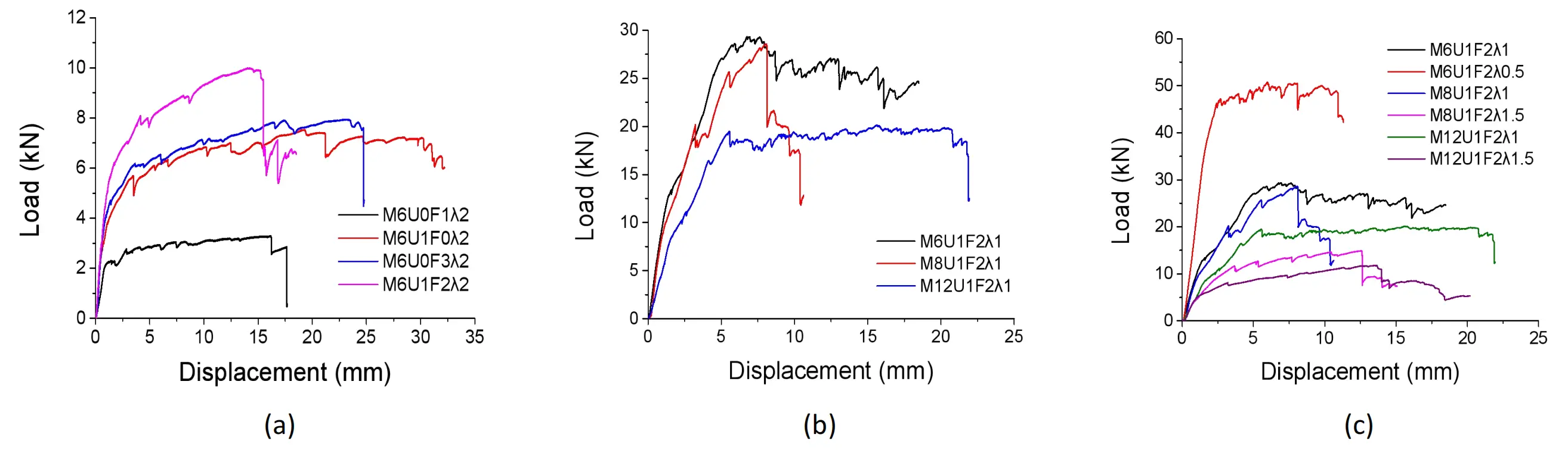
Figure 6. The effect of various factors on Load displacement graphs of sample: (a) U-shape steel wire mesh; (b) Grid size of steel wire mesh; (c) Shear span ratio.
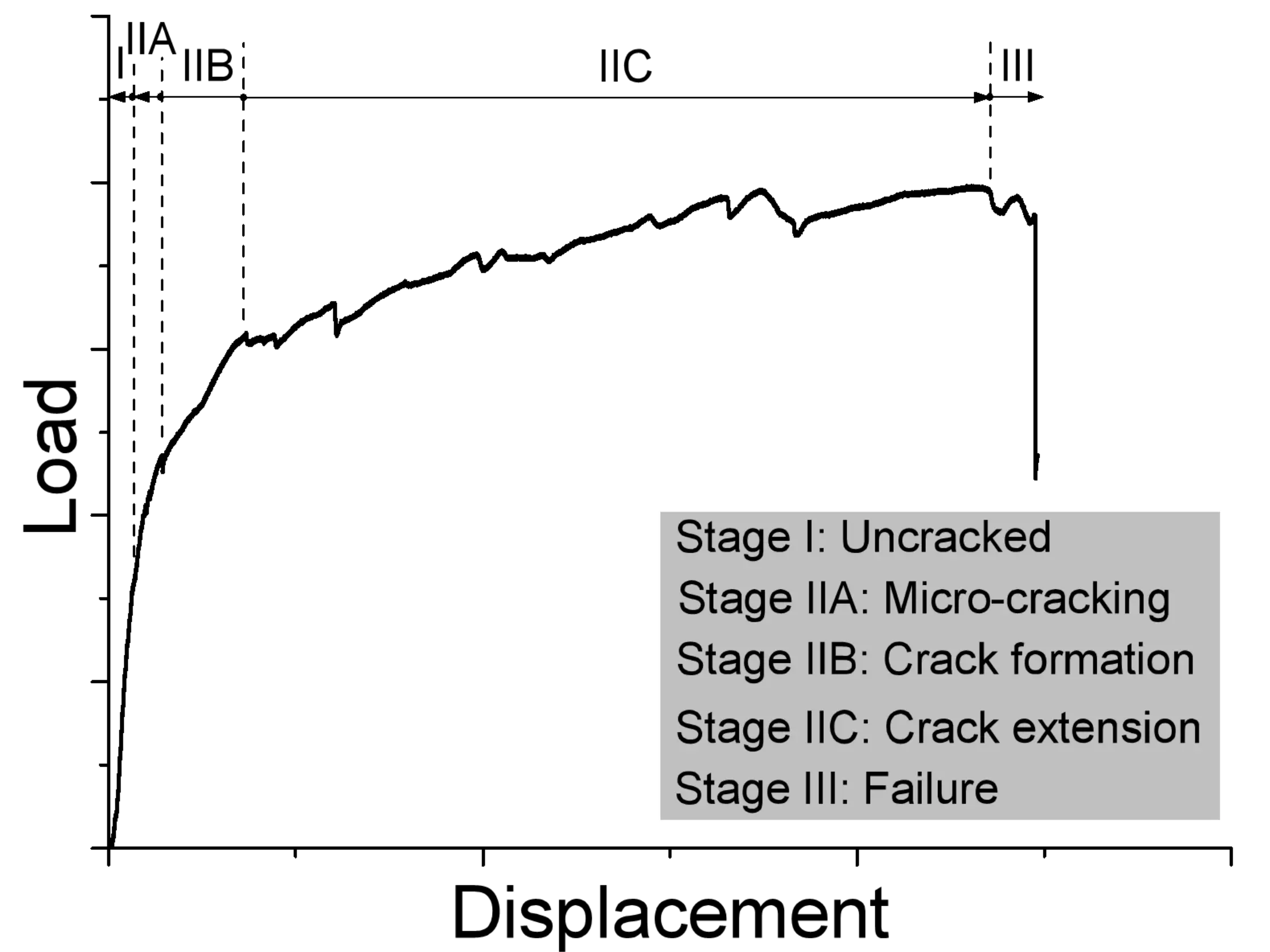
Figure 7. Typical load versus displacement for a specimen under four-point bending, with indicated stages.
As shown in Figure 6a and Table 3, the control sample M6U0F1λ2, reinforced with a one-layer SWM, failed at a load of 3.3 kN with a displacement of 16.2 mm. In contrast, the sample M6U1F0λ2, reinforced with a single layer of U-shape SWM, failed at a load of 7.2 kN and displacement of 30.3 mm, corresponding to improvements of 118% in load-bearing capacity and 87% in displacement compared to the control specimen. Furthermore, the specimen incorporating one layer of U-shape SWM and two layers of flat SWM, exhibited a 27% increase in ultimate load-bearing capacity but a 37% reduction in failure displacement, compared with the sample employing three layers of flat steel wire mesh.
Figure 6b and Table 3 indicate that the use of U-shape SWM with various grid sizes enhanced the failure bearing capacity while markedly reducing displacement at failure. Specifically, the sample strengthened with a U-shape SWM of 12 mm grid size failed under a load of 18.7 kN. In comparison, specimens with 6 mm and 8 mm grid sizes achieved approximately 40% and 53% higher load capacities, respectively, relative to the 12 mm grid specimen. Additionally, compared to the specimen with a 12 mm grid size, these specimens demonstrated reductions in displacement at failure of approximately 27% and 62%.
As shown in Figure 6c and Table 3, the specimen M6U1F2λ0.5, reinforced with U-shape SWM and a shear span ratio (λ) of 0.5, demonstrated the highest load-bearing capacity and the smallest displacement at failure. The load-bearing capacity decreased with increasing shear span ratio, reflecting a shift from compression-shear to bending-shear stress states. Furthermore, samples reinforced with U-shape SWM of smaller grid sizes exhibited higher load capacities than those with larger sizes.
4.2 Failure mode and cracking behavior of concrete
The experimental failure specimens are presented in Figure 8 and summarized in Table 3. The application of U-shape SWM could enhance the property of the printed composites. Specifically, M6U0F1λ2, reinforced with a single layer of flat SWM, displayed the fewest cracks (5) between the loading points and failed due to SWM rupture. This showed a clear flexural failure mode without shear cracks. In contrast, M6U0F3λ2 developed more fissures in the flexural zone and generated inclined shearing cracks within the shearing regions. M6U1F0λ2 experienced flexural failure accompanied by the concrete crushing, while M6U1F2λ2 exhibited flexural cracks and concrete flattening under a comparatively higher load. These observations suggest that U-shape SWM significantly alleviates the formation of shearing cracks.
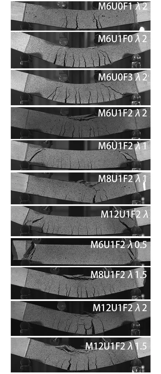
Samples with a shearing span ratio (λ) of 1 (M6U1F2λ1, M8U1F2λ1, and M12U1F2λ1) exhibited numerous cracks, primarily located between the two loading points, as shown in Figure 8. Oblique shear cracks developed in the shear regions (from supports to loading points), and evolved into ultimate failure cracks in specimens M6U1F2λ1 and M12U1F2λ1. Conversely, M8U1F2λ1 showed fewer and less pronounced oblique shear cracks, which only extended to mid-height and did not reach the loading points. Other cracks remained confined to regions near the loading points. Notably, a flexural crack near the mid-span of M8U1F2λ1 rapidly extended to four-fifths of the specimen’s height and became the primary failure crack, coinciding with concrete crushing in the compression region at mid-span.
M6U1F2λ0.5 manifested compression shearing failure similar to that of M6U1F2λ1 and M12U1F2λ1. Only shearing cracks were observed in this specimen, and no flexural cracks developed. The remaining three specimens in Figure 8 (M8U1F2λ1.5, M12U1F2λ2, and M12U1F2λ1.5) experienced flexural failure accompanied by concrete crushing.
4.3 The effect resulting from the reinforcement of U-shape SWM
U-shape SWM improved the flexure performance of the tested composite specimens, as evidenced by higher failure load-carrying capacity and greater displacement at failure. As illustrated in Figure 6a, the load-displacement graph exhibits similar forms, but the failure load-bearing capacities of the samples differ significantly. Figure 9 compares the ultimate failure loads and corresponding displacements for samples with and without U-shape SWM.
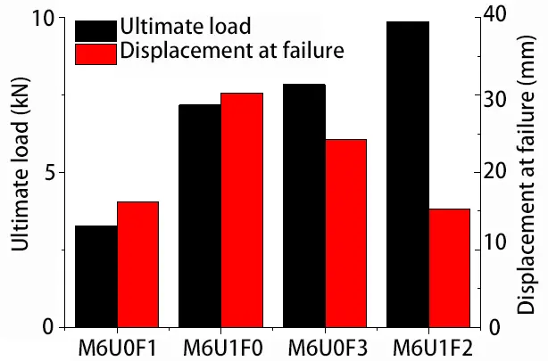
Figure 9. Comparison of test results (ultimate load capacity and displacement at failure) for samples with and without U-shape SWM reinforcement. U-shape SWM: U-shaped steel wire mesh.
M6U1F0λ2 (reinforced with U-shape SWM) showed a 118% higher failure load-bearing capacity and an 87% larger displacement at failure than those of M6U0F1λ2 (reinforced with flat SWM). M6U1F2λ2 (reinforced with one U-shape SWM and two flat SWM layers) exhibited a 27% higher failure load-bearing capacity but a 37% lower displacement at failure compared to M6U0F3λ2 (with three flat SWM layers). Notably, M6U1F0λ2 achieved the ultimate load capacity similar to that of M6U0F3λ2. In other words, the reinforcement provided by a single layer of U-shape SWM is comparable to that achieved with three layers of flat SWM.
Specimens reinforced with U-shape SWM showed a notable improvement in failure mode. More cracks were observed in specimen M6U1F0λ2 than in M6U0F1λ2, indicating that M6U1F0λ2 displayed greater ductility (Figure 10).
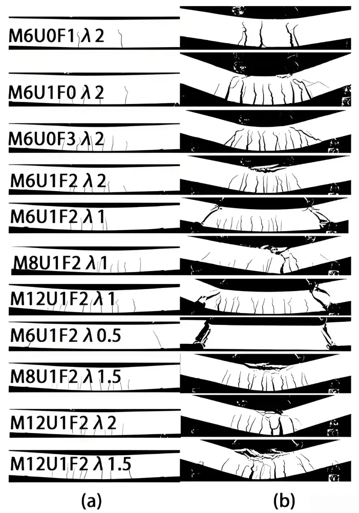
Figure 10. Cracking pattern under various loads: (a) Service load; (b) Ultimate load.
Specimen M6U1F2λ2 exhibited concrete crushing at failure but did not develop oblique shear cracks, while M6U0F3λ2 showed such cracks. This can be attributed to the vertical sections of the U-shape SWM, which improve the shearing strength of the composite material and thereby reduce inclined shearing cracks.
4.4 The influence of grid size of SWM reinforcement
Figure 11 illustrates the failure loads and corresponding displacements for samples reinforced with U-shape SWM of various mesh sizes. Specimen M6U1F2λ1 (with mesh size of 6 mm) demonstrated a 40% higher load capacity and an 27% lower displacement at failure compared to those of Specimen M12U1F2λ1 (with mesh size of 12 mm). Both test samples failed due to inclined shearing cracks. M8U1F2λ1 (with mesh size of 8 mm) exhibited higher load capacity and larger displacement than Specimens M6U1F2λ1 and M12U1F2λ1 up to reinforcement yielding, which occurred at a load of 25.6 kN. However, unlike the other two Specimens, Specimen M8U1F2λ1 failed abruptly, exhibiting a brittle failure mode that resembles the behavior of over-reinforced beams (Figure 6b and Figure 9). This can stem from the intermediate reinforcement ratio associated with the 8 mm mesh size, which provides substantial confinement in the tensile zone but limits strain compatibility between the concrete matrix and the steel wire mesh. As a result, the U-shaped SWM reached its yield stress before significant concrete cracking or internal stress redistribution occurred. This leads to premature crushing of the concreat in the compression zone, preventing the development of ductile flexural or flexure-shear behavior. In contrast, the specimen with a smaller mesh size (6 mm) possessed a denser reinforcement distribution, promoting better stress transfer and crack control and thus leading to a more gradual post-cracking response. Conversely, the 12 mm mesh configuration provided less confinement and allowed wider crack propagation, showing a relatively more ductile response. Consequently, the brittle response of the 8 mm mesh specimen represents a transitional condition, where the reinforcement ratio is high enough to restrict tensile deformation but insufficient to fully delay compressive crushing, similar to the failure mechanism observed in over-reinforced concrete beams.
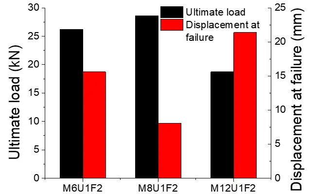
Figure 11. Comparison of test results (ultimate load capacity and displacement at failure) for specimens with U-shape SWM reinforcement and different mesh size. U-shape SWM: U-shaped steel wire mesh.
In general, the bearing capacity of 3DPC specimens improves with an increased U-shape SWM reinforcement ratio, achieved by reducing the grid dimension. This improvement is accompanied by a reduction in the width and quantity of shear crack, as depicted in Figure 8. Specifically, a finer mesh size effectively mitigates crack propagation, thereby reducing the severity and frequency of shear cracks.
4.5 Microstructural interpretation of experimental phenomena
While the mechanical tests provide valuable macroscopic insight into the effects of U-shape SWM reinforcement, the underlying mechanisms can be further elucidated from a microstructural perspective. Previous studies on fiber- and mesh-reinforced 3DPCs have revealed that layer interfaces often act as potential weak zones due to limited hydration bonding and entrapped pores[37-39]. Under loading, stress concentrations develop at these interlayer defects, promoting the formation of micro-cracks and subsequent delamination.
The vertical components of the U-shape SWM likely penetrate and bridge these weak interfaces, enhancing stress transfer continuity and reducing local sliding. This behavior is analogous to the crack-bridging mechanism in micro-reinforced cementitious composites, where interfacial shear stresses between the steel and the matrix delay crack opening[40]. Simultaneously, the horizontal mesh elements restrict lateral deformation and generate confinement near developing cracks, increasing aggregate interlock and frictional resistance. Accordingly, the U-shape SWM reinforcement promotes the formation of multiple fine cracks rather than a single dominant crack, as confirmed by the DIC observations and failure patterns discussed in Section 4.2.
In addition, Ruffray et al.[41] employed Focused Ion Beam-Scanning Electron Microscopy (FIB-SEM) nano-tomography to show that the steel-concrete interface contains nanoscale hydration layers and capillary pores, which significantly affect local anchorage. It is therefore reasonable that in the present U-shape SWM system, similar micro-locking and hydration densification occur around the embedded wires, contributing to the experimentally observed enhancement in shear resistance.
Although direct micro-scale testing (e.g., SEM, micro-CT, or FIB-SEM) was not performed in this study, future work should employ these techniques to validate the hypothesized mechanisms and quantitatively correlate the macroscopic behavior with microstructural features. Such analyses will provide a more comprehensive understanding of the stress-transfer efficiency, crack-bridging effects, and interfacial bonding characteristics of U-shape SWM-reinforced 3DPC.
5. Analytical Model
Accurately predicting the bearing capacity of reinforced 3D printing structural components remains challenging, despite extensive research on reinforcement strategies for printed concrete. The Strut-And-Tie Model (STM) has proven effective in estimating the shear failure load of traditional reinforced concrete beams[42]. In this research, a modified STM was fabricated specifically to evaluate shear bearing capacity of the printed concrete, integrating the influences of both U-shape SWM and flat SWM reinforcements within the shear span. The model’s accuracy was assessed by comparing its predictions with experimental results.
The proposed direct STM, as shown in Figure 12, represents stress transfer through steel bar connections and concrete props. Principal tensile stress f1 acts perpendicular to the diagonal strut, supported by both the SWM and the concrete’s tensile strength. Conversely, principal compressive stress f2 aligns with the diagonal strut, resisted by the compressive strength of the SWM and concrete[43,44].
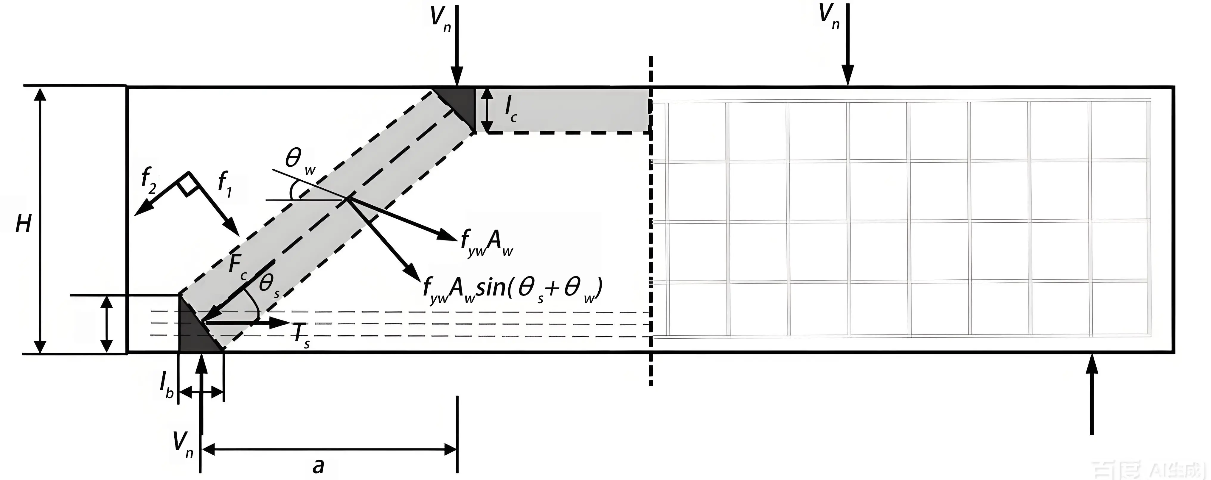
Figure 12. The ascertainment of compressive stresses and tensile at the STM nodes. STM: Strut-And-Tie Model.
According to the force balance at the bottom node of the diagonal brace in both vertical and horizontal directions, the following formulas can be constructed respectively:
where θs indicates the inclination angle of the diagonal brace; Fc represents the compressive stress of the diagonal pillar; Vn denotes the shear stress; and Ts shows the tension force in tie rod, which can be calculated as follows:
where a indicates the distance between the supports and stress measured from corresponding centerlines; lc and la represent the heights of the top and bottom side node areas, respectively; H expresses the sample height.
The compressive force f2 and principal tension force f1 at the compression-tension note can be expressed respectively as follows:
where k indicates an element that accounts for the non-uniform stress distribution of Tssinθs (assuming triangular stress distribution[45]), k = 2; Tssinθs/(Ac/sinθs) expresses the average equivalent tension of the diagonal struts; Astr denotes the transverse region of the diagonal pillar at the tension-compression panel point; Ac means the cross-sectional region of the beam.
where lb indicates the supports breadth; b means the beam width; and la expresses the bottom node profundity.
The failure criterion proposed for the bottom node is inferred from the assumption that the tensile and compressive stresses exhibit a linear relationship. It is modified from the Mohr-Coulomb theory by Tan et al.[46], and can be expressed as follows:
where ft represents the combined tensive intensity of both concrete and SWM reinforcement; fc′ denotes the concrete compressive strength, which is expressed as follows:
where fs is the contribution of the horizontal section of the U-shape SWM; fsw represents the contribution of the vertical sections of the U-shape SWM; and fct corresponds to the contribution of the concrete.
The term fs can be calculated as follows:
where fy indicates the horizontal steel yield intensity; As represents the total area of the SWM horizontal steel wires.
The term fsw can be calculated as follows:
where fyw means the vertical steel yield intensity; Aw indicates the total area of the SWM perpendicular steel wires; θw represents the angle between the vertical reinforcement at the intersection with the diagonal brace and the horizontal axis of the beam, accounting for the varying positions of the vertical reinforcement. The U-shape SWM reinforcement consists of three sections: the vertical reinforcement (perpendicular steel wires), the horizontal section, and longitudinal vertical reinforcement (longitudinal steel wires of the perpendicular SWM section). Hence, fsw can be rewritten as follows:
where Ash and Asv represent the total areas of longitudinal and vertical reinforcement respectively, within the shear span of the vertical SWM section.
The term fct expresses the concrete tensile strength and is based on Belarbi and Hsu[25]:
Where ε1 expresses the main tensile strain of the concrete pillar; εcr denotes the strain at the period of concrete cracking, taken as 0.00008[47] and can be calculated as:
where εs indicates the tensile strain of steel wire and ε2 represents the peak compressive strain of the concrete pillar at failure. Typically, ε2 is 0.002 and εs is 0.01.
Table 4 provides the calculated and predicted shear failure loads of the specimens reinforced with U-shape SWM, obtained using the developed model. It is worth noting that the term lc was initially uncertain, and was assumed equal to la for simplicity. Only four samples can be established, namely λ of 0.5 and 1.0, owing to the fact that θs in the STM model should exceed 25°.
Table 4. Predicted and test failure loadings for the samples.
| Specimen Designation | VCal/VTe | test Vn (kN) | computed Vn (kN) |
| M6U1F2λ1 | 1.1 | 13.1 | 14.4 |
| M8U1F2λ1 | 0.92 | 14.3 | 13.1 |
| M12U1F2λ1 | 1.16 | 9.4 | 10.9 |
| M6U1F2λ0.5 | 0.87 | 21.8 | 18.9 |
The predicted failure loads closely align with the test results, with the VCal/VTe ratio ranging from 0.87 to 1.16, yielding a mean value of 1.01 and a standard deviation of 0.139, as detailed in Table 4. This suggests that the proposed model offers reliable predictions. According to Collins’ modified demerit points classification (DPC)[37,38], the VCal/VTe ratio falls within the “appropriate safety” range (0.869 ≤ \(V_{\text{Cal}}/V_{\text{Te}} \) < 1.176), indicating satisfactory prediction accuracy[48,49]. The DPC classification system includes five categories: extremely dangerous (for VCal/VTe ≥ 2), dangerous (for 1.176 ≤ VCal/VTe < 2), appropriate safety (for 0.869 ≤ VCal/VTe < 1.176), conservative (for 0.5 ≤ VCal/VTe < 0.869), and extremely conservative (for VCal/VTe < 0.5).
It is imperative to define the boundaries of applicability for the proposed STM. The model was developed and validated based on a specific subset of the experimental data, particularly specimens with shear span-to-depth ratios (λ) of 0.5 and 1.0. This restricted scope arises from the fundamental assumption of the STM, idealizing load transfer mechanisms through compressive struts and tensile ties—a simplification most appropriate for structural members where shear behavior dominates, such as deep beams with λ ≤ 1.0. For members with larger shear span ratios (λ > 1.5), the structural response becomes increasingly flexure-dominated failure mechanisms. In such cases, the internal stress fields deviate significantly from the simplified load paths inherent to the current STM formulation, potentially compromising the model’s predictive accuracy. Consequently, the proposed STM is recommended primarily for predicting shear capacity of 3D printed concrete beams with a small shear span ratio (λ ≤ 1.0). Future research should aim to enhance the model’s generality by incorporating parameters that capture the interplay between flexural and shear behaviors, alongside extensive validation using a broader experimental dataset encompassing a wider range of shear span ratios and reinforcement configurations.
6. Conclusions
This study developed U-shape SWM reinforcement to provide shear resistance to 3DPC. An innovative fabrication technology combining U-shape SWM with an instrumentation equipped with an oblique print nozzle was developed to manufacture samples. The shear and flexure property of printed concrete reinforced with U-shape SWM was investigated experimentally. The key conclusions of this research can be summarized as follows:
(1) The ultimate bearing capacities and ductility of composite samples were significantly improved by adding SWM reinforcement to printed concrete. This improvement was more pronounced in samples with U-shape SWM reinforcement compared to those with flat SWM. The cross-sectional capacity is increased due to the increased shearing capacity provided by the vertical sections of the U-shape SWM. The flexural-shear property of the 3DPC is substantially enhanced by the combination of flat and U-shape SWM.
(2) U-shape SWM reinforcement restrained crack initiation and propagation, particularly under combined flexural-shear loading. The presence of vertical mesh elements improved the shear transfer between printed layers and limited the diagonal cracks.
(3) A smaller mesh grid increased load capacity but reduced ductility, consistent with an over-reinforced failure mode. The optimal reinforcement can be achieved by adjusting the grid scale to balance stiffness and deformation capacity.
(4) The bearing capacities of specimens reinforced with U-shape SWM were predicted by utilizing STM. The prediction model aligned well with the experimental observations, demonstrating the model’s reliability.
Although the proposed U-shape SWM reinforcement system shows significant potential for improving the mechanical performance of 3DPC, several challenges do exist. Future work should focus on improving the scalability and automation of the dual-arm robotic fabrication process to enable practical construction applications. Moreover, optimization of the reinforcement geometry and mesh configuration is necessary to balance ductility and strength across various structural forms. Further investigations on long-term durability, interfacial bonding under environmental exposure, and hybrid reinforcement systems combining fibers or continuous bars could enhance the overall structural reliability of 3D printed composites. Integrating numerical modeling and machine learning techniques may support the design optimization and real-time control of reinforcement during the printing process.
Authors contribution
Zhang G: Writing-review & editing, data curation.
Chen L: Writing-original draft, validation.
Sun J: Conceptualization, methodology.
Morsy AM: Formal analysis.
Ding H: Project administration.
He R: Investigation.
Luo X: Supervision.
Wang Y: Resource.
Conflicts of interest
Junbo Sun is the Executive Chief Editor of Journal of Building Design and Environmen. Genbao Zhang, Hiabin Ding are Youth Editorial Board Members of Journal of Building Design and Environmen. The other authors declare no conflicts of interest.
Ethical approval
Not applicable.
Consent to participate
Not applicable.
Consent for publication
Not applicable.
Availability of data and materials
The data and materials could be obtained from the corresponding author upon request.
Funding
None.
Copyright
© The Author(s) 2025.
References
-
1. Bai M, Xiao J, Ding T, Yu K. Interfacial bond properties between 3D printed engineered cementitious composite (ECC) and post-cast concrete. Cem Concr Compos. 2025;157:105897.[DOI]
-
2. Pham LT, Huang JY. 3D printed artificial coral reefs: Design and manufacture. Low-carbon Mater Green Constr. 2024;2(1):23.[DOI]
-
3. Sanjayan JG, Nematollahi B, Xia M, Marchment T. Effect of surface moisture on inter-layer strength of 3D printed concrete. Constr Build Mater. 2018;172:468-475.[DOI]
-
4. Wang L, Yang Y, Yao L, Ma G. Interfacial bonding properties of 3D printed permanent formwork with the post-casted concrete. Cem Concr Compos. 2022;128:104457.[DOI]
-
5. Hou S, Duan Z, Xiao J, Ye J. A review of 3D printed concrete: Performance requirements, testing measurements and mix design. Constr Build Mater. 2021;273:121745.[DOI]
-
6. Panda B, Tan MJ. Experimental study on mix proportion and fresh properties of fly ash based geopolymer for 3D concrete printing. Ceram Int. 2018;44(9):10258-10265.[DOI]
-
7. Shakor P, Sanjayan J, Nazari A, Nejadi S. Modified 3D printed powder to cement-based material and mechanical properties of cement scaffold used in 3D printing. Constr Build Mater. 2017;138:398-409.[DOI]
-
8. Sun J, Huang Y, Aslani F, Ma G. Electromagnetic wave absorbing performance of 3D printed wave-shape copper solid cementitious element. Cem Concr Compos. 2020;114:103789.[DOI]
-
9. Liu C, Wang X, Chen Y, Zhang C, Ma L, Deng Z, et al. Influence of hydroxypropyl methylcellulose and silica fume on stability, rheological properties, and printability of 3D printing foam concrete. Cem Concr Compos. 2021;122:104158.[DOI]
-
10. Wolfs RJM, Bos FP, Salet TAM. Early age mechanical behaviour of 3D printed concrete: Numerical modelling and experimental testing. Cem Concr Res. 2018;106:103-116.[DOI]
-
11. Das A, Reiter L, Mantellato S, Flatt RJ. Early-age rheology and hydration control of ternary binders for 3D printing applications. Cem Concr Res. 2022;162:107004.[DOI]
-
12. Sun J, Aslani F, Wei J, Wang X. Electromagnetic absorption of copper fiber oriented composite using 3D printing. Constr Build Mater. 2021;300:124026.[DOI]
-
13. Wolfs RJM, Bos FP, Salet TAM. Hardened properties of 3D printed concrete: The influence of process parameters on interlayer adhesion. Cem Concr Res. 2019;119:132-140.[DOI]
-
14. Ding T, Xiao J, Zou S, Wang Y. Hardened properties of layered 3D printed concrete with recycled sand. Cem Concr Compos. 2020;113:103724.[DOI]
-
15. Sun J, Huang Y, Aslani F, Wang X, Ma G. Mechanical enhancement for EMW-absorbing cementitious material using 3D concrete printing. J Build Eng. 2021;41:102763.[DOI]
-
16. Sun J, Aslani F, Lu J, Wang L, Huang Y, Ma G. Fibre-reinforced lightweight engineered cementitious composites for 3D concrete printing. Ceram Int. 2021;47(19):27107-27121.[DOI]
-
17. Nematollahi B, Vijay P, Sanjayan J, Nazari A, Xia M, Naidu Nerella V, et al. Effect of polypropylene fibre addition on properties of geopolymers made by 3D printing for digital construction. Materials. 2018;11(12):2352.[DOI]
-
18. Ali YMS, Abdelaleem T, Diab HM, Rashwan MMM. Effect of silica fume on the behavior of lightweight reinforced concrete beams made from crushed clay bricks. AI Civ Eng. 2023;2(1):3.[DOI]
-
19. Hambach M, Rutzen M, Volkmer D. Properties of 3D-printed fiber-reinforced portland cement paste. In: Sanjayan JG, Nazari A, Nematollahi B, editors. 3D-printed fiber-reinforced portland cement paste. United Kingdom: Butterworth-Heinemann; 2019. p. 73-113.
-
20. Arunothayan AR, Nematollahi B, Ranade R, Bong SH, Sanjayan J. Development of 3D-printable ultra-high performance fiber-reinforced concrete for digital construction. Constr Build Mater. 2020;257:119546.[DOI]
-
21. Bos FP, Bosco E, Salet TAM. Ductility of 3D printed concrete reinforced with short straight steel fibers. Virtual Phys Prototyp. 2019;14(2):160-174.[DOI]
-
22. Khoshnevis B, Hwang D, Yao K-T, Yeh Z. Mega-scale fabrication by contour crafting. Int J Ind Syst Eng. 2006;1(3):301-320.[DOI]
-
23. Bos FP, Ahmed ZY, Wolfs RJ, Salet TA. 3D printing concrete with reinforcement. In: Hordijk DA, Luković M, editors. High tech concrete: where technology and engineering meet: proceedings of the 2017 fib symposium; 2017 Jun 12-14; Maastricht, The Netherlands. Cham: Springer; 2017. p. 2484-2493.[DOI]
-
24. Lim JH, Panda B, Pham QC. Improving flexural characteristics of 3D printed geopolymer composites with in-process steel cable reinforcement. Constr Build Mater. 2018;178:32-41.[DOI]
-
25. Li Z, Wang L, Ma G. Mechanical improvement of continuous steel microcable reinforced geopolymer composites for 3D printing subjected to different loading conditions. Compos Part B Eng. 2020;187:107796.[DOI]
-
26. Perrot A, Jacquet Y, Rangeard D, Courteille E, Sonebi M. Nailing of layers: A promising way to reinforce concrete 3D printing structures. Materials. 2020;13(7):1518.[DOI]
-
27. Geneidy O, Kumarji S, Dubor A, Sollazzo A. Simultaneous reinforcement of concrete while 3D printing. In: Bos F, Lucas S, Wolfs R, Salet T, editors. Second RILEM International Conference on Concrete and Digital Fabrication. Springer, Cham; 2020. p. 895-905.[DOI]
-
28. Hass L, Bos F. Bending and pull-out tests on a novel screw type reinforcement for extrusion-based 3D printed concrete. In: Bos F, Lucas S, Wolfs R, Salet T, editors. Second RILEM International Conference on Concrete and Digital Fabrication.Springer, Cham; 2020 p. 632-645.[DOI]
-
29. Marchment T, Sanjayan J. Mesh reinforcing method for 3D concrete printing. Autom Constr. 2020;109:102992.[DOI]
-
30. Hack N, Dörfler K, Walzer AN, Wangler T, Mata-Falcón J, Kumar N, et al. Structural stay-in-place formwork for robotic in situ fabrication of non-standard concrete structures: A real scale architectural demonstrator. Autom Constr. 2020;115:103197.[DOI]
-
31. Asprone D, Auricchio F, Menna C, Mercuri V. 3D printing of reinforced concrete elements: Technology and design approach.Constr Build Mater. 2018;165:218-231.[DOI]
-
32. Vantyghem G, De Corte W, Shakour E, Amir O. 3D printing of a post-tensioned concrete girder designed by topology optimization. Autom Constr. 2020;112:103084.[DOI]
-
33. Salet TA, Ahmed ZY, Bos FP, Laagland HL. Design of a 3D printed concrete bridge by testing. Virtual Phys Prototyp. 2018;13(3):222-236.[DOI]
-
34. Naser MZ. Causality in structural engineering: Discovering new knowledge by tying induction and deduction via mapping functions and explainable artificial intelligence. AI Civ Eng. 2022;1(1):6.[DOI]
-
35. Warsi SBF, Panda B, Biswas P. Exploring fibre addition methods and mechanical properties of fibre-reinforced 3D printed concrete: A review. Dev Built Environ. 2023;16:100295.[DOI]
-
36. Bai M, Wu Y, Xiao J, Ding T, Yu K. Workability and hardened properties of 3D printed engineered cementitious composites incorporating recycled sand and pe fibers. J Build Eng. 2023;71:106477.[DOI]
-
37. Liu M, Zhang Q, Tan Z, Wang L, Li Z, Ma G. Investigation of steel wire mesh reinforcement method for 3D concrete printing. Archiv Civ Mech Eng. 2021;21(1):24.[DOI]
-
38. Liu M, Zhang Q, Tan Z, Wang L, Li Z, Ma G. Investigation of steel wire mesh reinforcement method for 3D concrete printing. Archiv Civ Mech Eng. 2021;21(1):24.[DOI]
-
39. Assaad JJ, Abou Yassin A, Alsakka F, Hamzeh F. A modular approach for steel reinforcing of 3D printed concrete—preliminary study. Sustainability. 2020;12(10):4062.[DOI]
-
40. Wang L, Ma G, Liu T, Buswell R, Li Z. Interlayer reinforcement of 3D printed concrete by the in-process deposition of U-nails. Cem Concr Res. 2021;148:106535.[DOI]
-
41. Ruffray N, Angst UM, Schmid T, Zhang Z, Isgor OB. Three-dimensional characterization of the steel-concrete interface by FIB-SEM nanotomography. arXiv:2310.04322 [Preprint]. 2023.[DOI]
-
42. Liu J, Mihaylov BI. A comparative study of models for shear strength of reinforced concrete deep beams. Eng Struct. 2016;112:81-89.[DOI]
-
43. Code CF. CEB-FIP model code for concrete structures, euro-international committe for concrete. Bulletin. 1990.
-
44. Canadian Standards Association. Design of concrete structures A23.3-94. Rexdale, ON: Canadian Standards Association; 1994.
-
45. Tan KH, Tong K, Tang CY. Direct strut-and-tie model for prestressed deep beams. J Struct Eng. 2001;127(9):1076-1084.[DOI]
-
46. Tan KH, Tang CY, Tong K. A direct method for deep beams with web reinforcement. Mag Concr Res. 2003;55(1):53-63.[DOI]
-
47. Belarbi A, Hsu TT. Constitutive laws of concrete in tension and reinforcing bars stiffened by concrete. Struct J. 1994;91(4):465-474.[DOI]
-
48. Neto BNM, Barros JAO, Melo GSSA. Model to simulate the contribution of fiber reinforcement for the punching resistance of RS slabs. J Mater Civ Eng. 2014;26(7):04014020.[DOI]
-
49. Collins MP. Evaluation of shear design procedures for concrete structures: a report prepared for the CSA Technical Committee on Reinforced Concrete Design. Toronto: Canadian Standards Association; 2001.
Copyright
© The Author(s) 2025. This is an Open Access article licensed under a Creative Commons Attribution 4.0 International License (https://creativecommons.org/licenses/by/4.0/), which permits unrestricted use, sharing, adaptation, distribution and reproduction in any medium or format, for any purpose, even commercially, as long as you give appropriate credit to the original author(s) and the source, provide a link to the Creative Commons license, and indicate if changes were made.
Publisher’s Note
Science Exploration remains a neutral stance on jurisdictional claims in published
maps
and institutional affiliations. The views expressed in this article are solely those
of
the author(s) and do not reflect the opinions of the Editors or the publisher.
Share And Cite


Science Exploration Style
Zhang G, Chen L, Liu M, Morsy AM, Ding H, He R, et al. Enhancing the shear properties of U-Shaped steel wire mesh reinforced 3D printed composites. J Build Des Environ. 2025;3:202567. https://doi.org/10.70401/jbde.2025.0020
Tips
Copy completed.
Submit a Manuscript
Author Instructions
Cite this Article
Article Metrics
0
View
0
Download
Cited
Article Updates

- Abstract
- Keywords
- 1. Introduction
- 2. Concept of U-shape SWM Manufacturing
- 3. Materials and Methods
- 4. Results and Discussions
- 5. Analytical Model
- 6. Conclusions
- Authors contribution
- Conflicts of interest
- Ethical approval
- Consent to participate
- Consent for publication
- Availability of data and materials
- Funding
- Copyright
Science Exploration Style
Zhang G, Chen L, Liu M, Morsy AM, Ding H, He R, et al. Enhancing the shear properties of U-Shaped steel wire mesh reinforced 3D printed composites. J Build Des Environ. 2025;3:202567. https://doi.org/10.70401/jbde.2025.0020
copy
Share Link
copy