Investigation of wheel-rail wear reduction by using MRF rubber joints with bidirectional adjustable stiffness Download PDF
Ning Gong
1,2

,
Jian Yang
3
,
Weihua Li
4
,
Shuaishuai Sun
1,2,*
*Correspondence to:
Shuaishuai Sun, CAS Key Laboratory of Mechanical Behavior and Design of Materials, School of Engineering Science, University of Science and Technology of China, Hefei 230027, Anhui, China.
E-mail: sssun@ustc.edu.cn
Smart Mater Devices. 2025;1:202530. 10.70401/smd.2025.0018
Received: August 07, 2025Accepted: September 29, 2025Published: September 30, 2025
Abstract
Stiffness of the primary longitudinal rubber joints is critical for both the high-speed stability and curve trafficability of the train. However, existing joints with fixed stiffness inevitably generate large wheel-rail lateral forces and wear on curves. To address this issue, a fail-safe rubber joint incorporating magnetorheological fluid (MRF) technology is proposed, enabling bidirectional variable stiffness. First, the structure and working principle of MRF rubber joint are described in detail. Subsequently, prototypes of the MRF damper and the MRF rubber joint are assembled and tested, yielding satisfactory variable damping and stiffness performance. Moreover, dynamic simulations further demonstrate the joint’s effectiveness in improving both stability and curve trafficability. A control algorithm based on track curvature identification is also proposed. The co-simulation results validate the potential of the MRF rubber joint on reducing wheel-rail wear and enhancing safety of trains.
Keywords
MRF rubber joint, fail-safe characteristic, high-speed stability, curve trafficability, wheel-rail wear
1. Introduction
Railway transportation is one of the most common and environmentally friendly public transportations in the world, with high-speed railways in particular significantly enhancing passenger mobility by reducing travel time and spatial distances. Wheel-rail wear remains an unavoidable issue which is closely related to train safety and operational maintenance costs[1]. Studies show that trains undergo more wear when traveling on curves than on straight tracks[2]. It’s critical that improving the curve trafficability is the most basic and effective measure to reduce wheel-rail wear. Various engineering strategies have been explored to reduce this wear, including the use of worn tread[3], optimization of lubrication conditions[4], and wheel reprofiling[5]. In addition to improving the wheel-rail contact, researches demonstrate that smaller primary longitudinal stiffness is helpful to improve the curve trafficability and reduce wear[6]. However, it cannot be ignored that the primary longitudinal stiffness also has a significant impact on both curve trafficability and high-speed stability, which has conflicting stiffness requirements. Consequently, it is urgent to propose a controllable bogie technology that can take into account both high-speed stability and curve trafficability performance.
In order to simultaneously enhance the high-speed stability and the curve passing ability, several researches have been proposed from passive steering bogies[7,8], active steering bogies[9-11], and semi-active bogies with controllable suspensions[12,13]. Yang et al.[14] developed a new bogie with independently rotating wheels to enhance its self-steering ability, which improved the performance by possessing the self-centering ability on straight tracks and decreasing the anti-yaw stiffness on curves. Luo et al.[15] proposed an interconnected hydro-pneumatic suspension system which allows the front and rear wheelsets to yaw in the opposite direction. The general passive steering has achieved satisfactory performance in reducing the wear, however, it becomes challenging to tackle the increasing velocity of high-speed trains with constant stiffness. Stichel et al.[16] proposed an active hydraulic actuator in the wheelset steering system that effectively reduced wear on curved tracks. Hur et al.[17] developed an active steering bogie and tested its effectiveness on reducing the wheel noise in curved section. In order to enhance the safety-critical issues, Fu et al.[18] introduced a fault-tolerant approach based on risk priority number, enhancing the reliability of active steering bogie. Despite the fact that active suspension can improve the curve trafficability of trains and reduce wear, it also leads to higher energy consumption and hardware costs.
Considering both stability and commercial viability, increasing attention has been directed toward semi-active controllable bogie technology. Magnetorheological (MR) materials such as magnetorheological fluid (MRF) and magnetorheological elastomer (MRE) are smart ones with controllable stiffness or variable damping with external magnetic field, which show huge potentials in dampers[19-22], clutches[23,24], and isolators[25,26]. Many researches illustrates that the dynamic of trains is sensitive to the secondary lateral damping[27,28] and primary longitudinal stiffness. Magnetorheological technology in secondary suspension of railway vehicles has been widely studied to improve the critical speed and comfort[29,32]. Rubber joint is the significant component of primary suspension of bogie, which connects the axle box and the bogie frame. Recently, a few studies have begun to investigate variable primary longitudinal rubber joint. Shin et al.[33] proposed an MRE rubber joint which achieves 30% stiffness change at 15% shear strain. Yang proposed a shear thickening fluid rubber joint based on different excitation frequency, which achieves a 170.4% stiffness changing rate[34]. Building upon MR materials, our previous work have proposed an MRF rubber joint[35] and an MRE rubber joint[36], which achieves an absolute stiffness changes of 0.65 MN/m and 0.28 MN/m, with relative rates of change of 97% and 74.7%, respectively. However, the stiffness tuning ranges achieved in these designs remain limited and the design criteria of positive stiffness with power supply may not provide sufficient stiffness in the event of a control system failure. In addition, the stiffness of the rubber joints we previously designed is much lower than the true value of commercial rubber joints for trains, and the absolute change in adjustable stiffness is relatively small. The typical stiffness of rubber joint for high-speed trains is about 10~15 MN/m[37,38]. As a result, it’s significant to investigate a new rubber joint with more obvious MR effect and fail-safe characteristic in the actual stiffness range.
To meet these requirements, a new MRF rubber joint with bidirectional adjustable stiffness was proposed. The MRF damper energized by the electromagnetic field and permanent magnetic field enables the new MRF rubber joint to achieve a bidirectional adjustable stiffness, which means a relatively large stiffness to ensure fail-safe characteristic. In addition, the bidirectional adjustable stiffness enhances MR effect while eliminating the need for large electromagnetic coils with high power consumption. The reminder of this paper is organized as follows. Section 2 presents the design and the working principle of the new MRF joint. Section 3 presents the experimental characterization of the MRF rubber joint. In Section 4, the numerical evaluation of the MRF rubber joint to improve the stability and trafficability of trains is conducted. Section 5 draws the conclusions.
2. Structural Design of MRF Rubber Joint
2.1 Structural design and working principle of the MRF rubber joint
As shown in Figure 1a, MRF rubber joint is the key component connecting the axle box and bogie frame, which determines the primary longitudinal stiffness. It works as an elastic joint which allows the wheel to adapt to the curvature of tracks. The MRF rubber joint requires a large longitudinal stiffness to suppress the hunting motion in straight tracks, while it needs to reduce the longitudinal stiffness to adapt to the curve track. In this case, a variable stiffness rubber joint makes it accessible to solve this conflicting requirement.
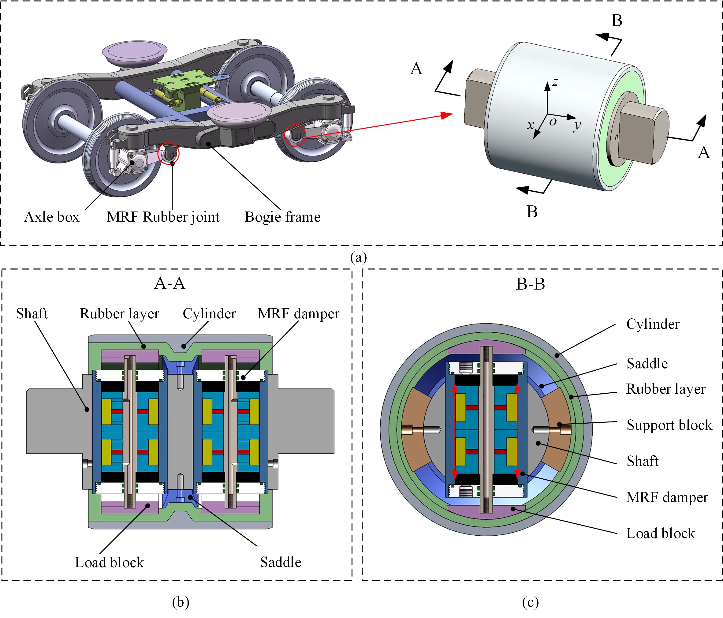
Figure 1. Structural design of the MRF rubber joint. (a) Installing position of MRF rubber joint; (b) Top sectional view of the MRF rubber joint; (c) Left sectional view of the MRF rubber joint. MRF: magnetorheological fluid.
The detailed structures of the MRF rubber joint are illustrated in Figure 1b,c. The MRF rubber joint is consisted of shaft, rubber layer, cylinder, MRF damper, load block, and saddle. The shaft is a cylindrical part with two central holes inside the axial direction, which provide the installing space for MRF dampers. In terms of the mechanical connection of MRF rubber joint, the milling platform at both ends of the shaft are used to match the bogie frame slots to transmit the longitudinal force of the train. The cylinder is tightly held by the rotary arm of axle box. Close to the cylinder, a polyurethane rubber layer is incorporated to provide the initial primary longitudinal, lateral, and vertical stiffness. The role of the rubber layer is to enable the rubber joint to deform elastically, thereby achieving the small amplitude of movement of the wheelset. It’s noticeable that these two MRF dampers are integrated in the shaft and primarily serve to modulate the longitudinal stiffness. The damping force is transmitted through the load block on the top of MRF dampers. Since the MRF rubber joint mainly transmits the longitudinal traction force of the wheelset, any relative movement between the axle box and bogie frame induces longitudinal deformation along the direction of x as shown in the Figure 1a. As a result, the piston of the MRF damper moves upward and downward, thereby driving the liquid flow in the two chambers on both sides, achieving the damping effect. Its flow takes place within the annular flow channel of the damper, as indicated by the red arrow in Figure 1c. In the axial direction of MRF rubber joint, a saddle is designed to provide lateral stiffness and prevent lateral movement of rubber layer. Four supporting blocks are arranged on the circumferential surface of the shaft and fit tightly with the rubber layer.
The working principle of the MRF rubber joint lies in the modulation of damping force controlled by the electromagnetic field. In order to more intuitively illustrate the principle of variable stiffness, we proposed a simplified physical model of the rubber joint as shown in Figure 2. According to the different stress areas of the rubber layer, the rubber layer can be approximately divided into three types of areas, namely the side rubber layer, top rubber layer, and the middle rubber layer, which can be considered as 5 parallel springs. The mathematical model is given as:
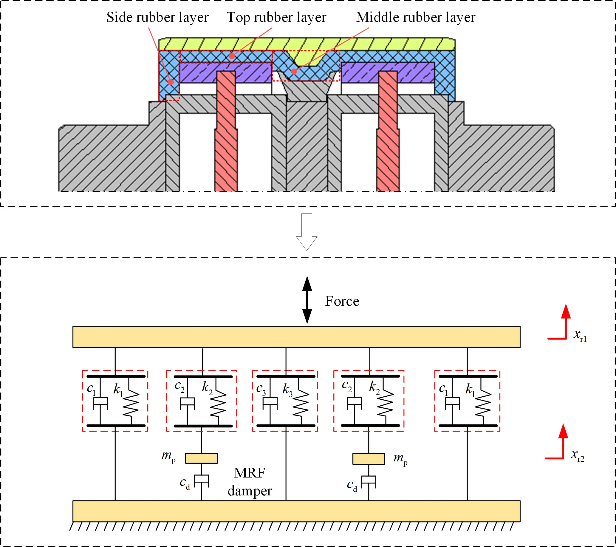
where F is the output force of the joint, k1 and c1 are the stiffness and the damping of the side rubber layer; k2 and c2 are the stiffness and the damping of the top rubber layer; k3 and c3 are the stiffness and the damping of the middle rubber layer; xr1 and xr2 are the displacement of cylinder and the load block; mp is the mass of the load block; cd is the damping of the MRF damper.
The stiffness output of the rubber joint is determined by the support condition of its top layer, which is controlled by the MRF damper. A low damping force that permits free piston motion drastically reduces this support, leading to low joint stiffness. In the theoretical limit of zero damping (cd = 0), the joint stiffness converges to the baseline value of 2k1 + k3. On the contrary, a high damping force imposes a constraint on the deformation of the top rubber layer, leading to an increase in the overall longitudinal stiffness of the joint. Under the idealization of an infinite damping coefficient (cd = ∞), the piston becomes completely locked. This represents the upper stiffness bound of the system, given by 2k1 + k3 + 2k2. When controlling the damper to output a middle damping coefficient, the piston will slide with different damping forces, thereby regulating the overall stiffness of the rubber joint. As a result, the longitudinal stiffness of the MRF rubber joint can be adjusted by the controllable electromagnetic field.
2.2 Structural design of the MRF damper
The adjustable range of the damping force of the MRF damper is an important factor affecting the change effect of the whole rubber joint. In order to achieve optimal performance, an MRF damper with bidirectional adjustable damping force was proposed. The damper can be controlled by the electromagnetic field and permanent magnetic field, enabling bidirectional damping adjustment which can enhance the MR effect while eliminating the need for a large coil with considerable power consumption. Figure 3a illustrates the structure of the new MRF damper with bidirectional adjustable damping. It’s composed of cylinder, piston, piston rod, end cap, sealing rings, coils, magnets, and MRF. The main parameters of the MRF damper are listed in Table 1.
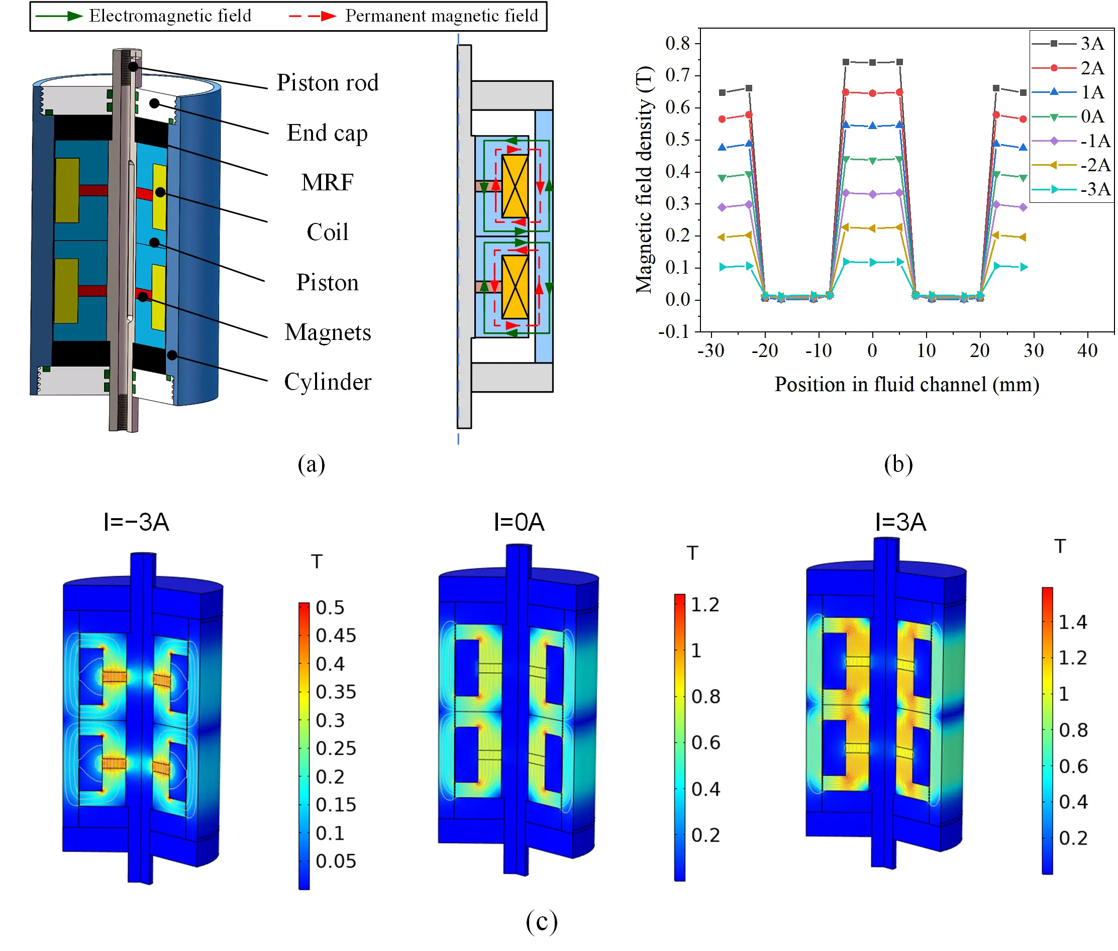
Figure 3. Structural design of the MRF damper. (a) Installing position of MRF rubber joint; (b) Magnetic field density along the fluid channel; (c) Magnetic field distribution of the MRF damper with varying currents. MRF: magnetorheological fluid.
Table 1. main parameters of the MRF damper.
| Parameter | Value | Parameter | Value |
| Outer diameter of cylinder | 52 mm | Width of piston | 5 mm |
| Inner diameter of cylinder | 40 mm | Coil width | 18 mm |
| Outer diameter of piston | 39.5 mm | Coil turns | 300 |
| Inner diameter of piston | 10 mm | Thickness of magnet | 3 mm |
MRF: magnetorheological fluid.
The proposed MRF damper is working based on the shear-valve mode, with an annular channel gap of 0.25 mm, which is located between the piston and the cylinder. Due to the double-ended structure, when the liquid moves in the annular channel, the volume changes of the two chambers can compensate for each other. The damping force is controlled by a hybrid magnetic field provided by the magnets and coils. To enhance the MR effect and reduce the heating of coils, the coils were designed as two sets of smaller coils wrapped on the pistons. These two magnets used are axially magnetized NdFeB magnets with opposite magnetic poles. It is worth mentioning that the piston rod was made of stainless steel to prevent the magnet from leaking magnetic flux and ensure that a closed circuit is formed from the piston. Two axial magnetized permanent magnets are added to the proposed damper to ensure an initial magnetic field, as shown in red dashed arrow in Figure 3a, which relates to a large damping force even in the absence of electricity. Additionally, these two permanent magnetic field circuits are symmetrically distributed between the two pistons in MRF damper. When the coils are energized with currents of 3 A and -3 A, electromagnetic fields are generated in the same and opposite directions as the original permanent magnetic field, respectively. This results in an enhanced hybrid magnetic field in the former case and a weakened one in the latter. Consequently, the magnetic field intensity in the flow channel reaches two extreme values, producing significantly different damping forces. The green arrow in Figure 3a shows the schematic diagram of weakening the magnetic field when the current is -3 A.
The magnetic field loop is shown by the red dashed lines and arrows in Figure 3a. As shown in Figure 3b,c, a magnetic field analysis was conducted in COMSOL software. Multiple probes are set up from top to bottom along the flow channel to measure the magnetic field strength of the magnetorheological fluid at different positions. The magnetic fields with varying currents are shown in Figure 3b. It can be seen that the magnetic field density on the piston circumference is much greater than that on the outside of the coil. Based on the positive and negative currents, the maximum magnetic field can vary from about 117 mT to 741 mT. The specific distributions of magnetic field under currents of -3 A, 0 A, and 3 A can be seen from Figure 3c. It shows that the magnets can provide an initial magnetic field, which means a considerable damping force. When energizing the coils with positive or negative current, it will weaken or strengthen the magnetic field inside the channel, which allows a bidirectional adjustable damping.
3. Experimental Characterization
3.1 Prototype of the MRF damper and variable damping testing
The MRF damper is the most critical device in the rubber joint whose performance directly affects the variable stiffness effect of the rubber joint. Therefore, it is necessary to test and verify the performance of MRF damper firstly. The components of MRF damper prototype is shown in Figure 4a. After completing the assembly of the prototype, the damping characteristic is tested by MTS Criterion 43 machine. The piston rod and cylinder of the MRF damper was connected to two clamps, as shown in Figure 4b. The force-displacement of the damper at different currents can be tested by driving the machine frame at a designated motion. Under a sinusoidal wave with frequency of 0.5 Hz and an amplitude of 4 mm, the damper was tested across a range of input currents, and the testing results were shown in Figure 5. As can be seen from Figure 5a, the damping force will have an obvious change with the varying currents. It can be seen that as a positive current is applied, the area of the force displacement loop gradually decreases, indicating a corresponding increase in the damping coefficient. The force-velocity loop is shown in Figure 5b, which demonstrates a distinct damping adjusting performance. In the test, the damping force of the MRF damper is about 2.95 kN without power supply. It can achieve a maximum damping force of about 7.48 kN and a minimum damping force of 0.41 kN at 3 A current and -3 A current, respectively. When operating at a maximum current of 3 A, the power consumption of a single damper is about 44.2 W. The damping force can be adjusted by around 18.2 times, thereby offering a wider range of tunability for the MRF rubber joint.
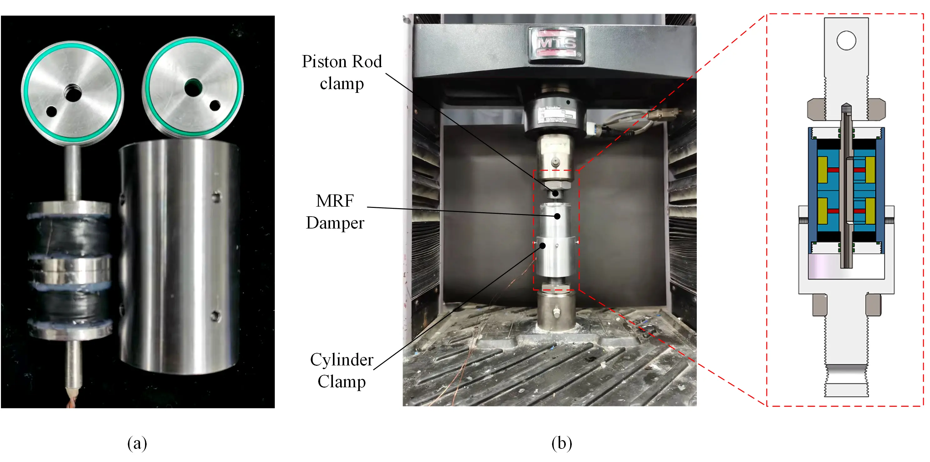
Figure 4. Prototype and the experimental setup of the MRF damper. (a) Components of MRF damper; (b) Experimental setup of the MRF damper. MRF: magnetorheological fluid.
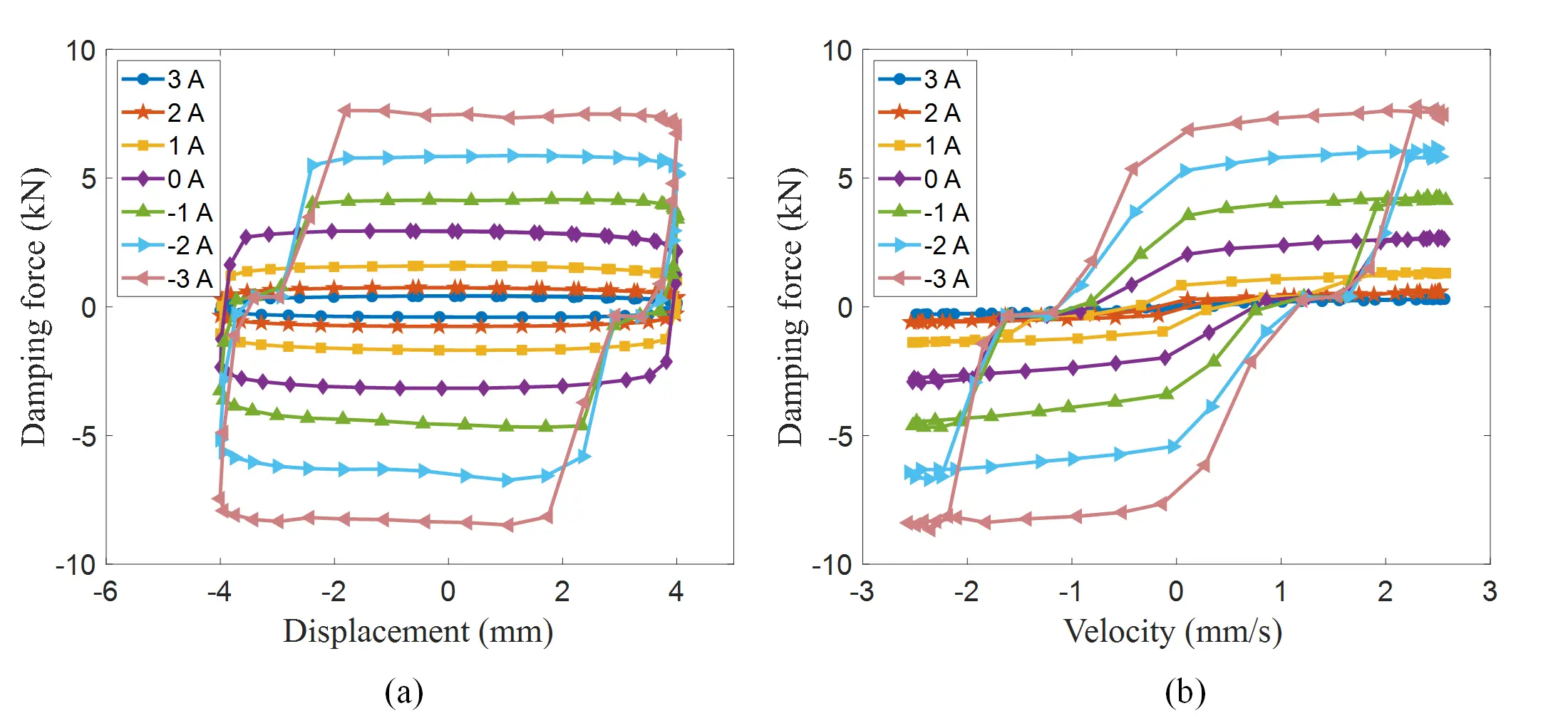
Figure 5. Testing results of the MRF damper. (a) Force-displacement loop of the MRF damper; (b) Force-velocity loop of the MRF damper. MRF: magnetorheological fluid.
3.2 Prototype of the MRF rubber joint and variable stiffness testing
After verifying the superior variable damping effect of the MRF damper, it was integrated with other components to assemble the final rubber joint. In order to meet different stiffness requirements, this study investigated two types of rubber joints with different stiffness ranges, achieved by replacing different rubber layers. The detailed characterization and analysis are introduced as follows.
3.2.1 MRF rubber joint prototype A with soft stiffness
Firstly, a softer MRF rubber joint is fabricated and assembled. The physical components used in the MRF rubber joint are shown in Figure 6a. The MRF damper is assembled into the shaft hole, followed sequentially by the saddle, load block, support block, rubber layer and cylinder. The rubber layer was made by Ecoflex 0030 which has a Shore hardness of 30 A.
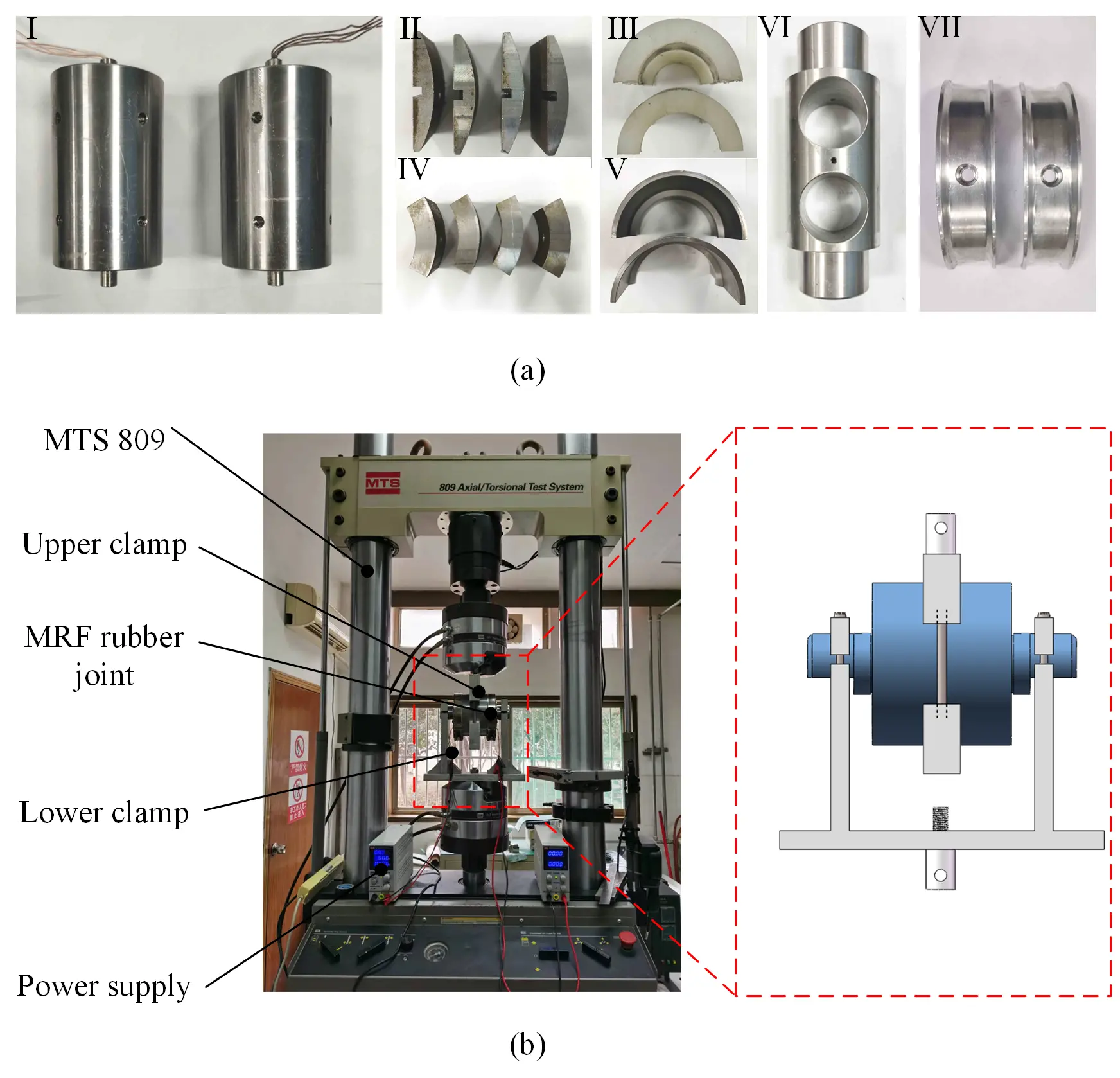
Figure 6. Prototype and the experimental setup of the MRF rubber joint. (a) Components of MRF rubber joint: I-MRF damper; II-load block; III-rubber layer; IV-supporting block; V-cylinder; VI-shaft; VII-saddle; (b) Experimental setup of the MRF rubber joint. MRF: magnetorheological fluid.
The assembled MRF rubber joint and experimental setup are shown in Figure 6b. The MRF rubber joint was tested on MTS 809 machine. To produce a controllable radial relative displacement, two custom-designed upper and lower clamps were fabricated to connect the outer cylinder and shaft of the rubber joint, respectively. The step of the lower clamp is precisely aligned with the milling plane of shaft in rubber joint, so that the damper shaft installation was exactly perpendicular, thereby meeting the requirements for reciprocating tension and compression. The MTS machine was programmed to displace the joint at a sinusoidal motion with a frequency of 0.5 Hz. To evaluate the variable stiffness performance of MRF rubber joint, three sets of displacements were selected to test the joint.
The testing results were illustrated in Figure 7. It can be seen that the force displacement curves of the rubber joint exhibit significant nonlinear spring characteristics. The slope of the curve represents the stiffness of the rubber joint under the current displacement and current state. In the force-displacement loop, the effective stiffness of rubber joint ke can be calculated as:
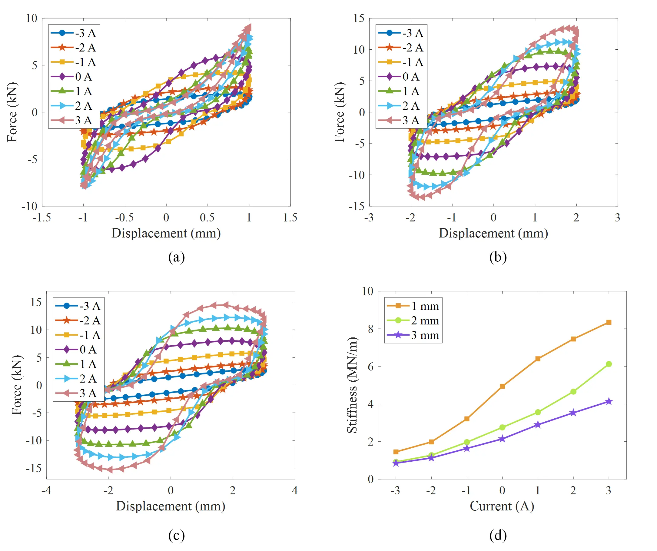
Figure 7. Testing results of the MRF rubber joint. (a) Force-displacement loop under amplitude of 1 mm; (b) Force-displacement loop under amplitude of 2 mm; (c) Force-displacement loop under amplitude of 3 mm; (d) Effective stiffness variation with currents. MRF: magnetorheological fluid.
where Fmax and Fmin are the maximum force and minimum force of the force-displacement loop, Δmax and Δmin are the maximum and minimum displacements of the loop.
As shown in Figure 7a, the proposed rubber joint exhibits a pronounced variable stiffness effect. As the current gradually changes from -3 A to 3 A, it can be seen that the output force of the rubber joint is correspondingly increasing, indicating a progressive enhancement in stiffness. Moreover, with increasing stiffness, the force-displacement loop of the rubber joint gradually transitions from damping characteristics to stiffness characteristics. In terms of the testing results of the other two displacements in Figure 7b,c, the MRF rubber joint also exhibits a satisfactory variable stiffness capability. It is interesting to see that the characteristics are a little different when testing negative current at small amplitudes and large amplitudes. It can be seen that the rubber joint tested with small amplitude will behave like a spring, while the testing of large amplitude will show larger damping characteristics at maximum stiffness than the data under 1 mm amplitude with same current. This is mainly because the damping force is sufficient enough to lock the top rubber layer during large amplitude testing, preventing piston movement. As a result, it mainly shows the stiffness characteristic of rubber layer which is nearly fixable with the changing of negative current. However, when the damping force is insufficient to lock the top rubber layer during large amplitude testing, the piston will move, resulting in a more obvious damping effect.
The calculated stiffness values are plotted in Figure 7d, with detailed numerical results under different conditions in Table 2. Consistent with the principle of the damper, the stiffness of the rubber joint has a large initial value of 4.94 MN/m in the de-energized state. Its stiffness will increase greatly to 8.34 MN/m when applying a current of 3 A, while it can reduce to about 1.45 MN/m when applying a current of -3 A. The proposed MRF rubber joint achieved a maximum stiffness variation capability of nearly 6.89 MN/m at the amplitude of 1 mm. The change ratio between the maximum and the minimum stiffness reached 5.75, and the proposed rubber joint also showed significant stiffness variation effects under displacement conditions of 2 mm and 3 mm. Under three different displacements, the proposed rubber joint achieved an average relative change rate of about 160.6% in bidirectional stiffness adjustment compared to the basic stiffness without electricity. As shown in Figure 7d, it can be clearly seen that the stiffness gradually decreases with the increase of displacement. This is because the damping force is not enough to lock the top rubber layer at larger amplitudes. When the damping force cannot support the top rubber layer anymore, the stiffness contribution of this layer diminishes and eventually disappears. As a result, the overall stiffness decreases under large displacement conditions.
Table 2. Effective stiffness of the MRF rubber joint prototype A.
| Currents | -3A | -2A | -1A | 0A | 1A | 2A | 3A | relative changing rate |
| Stiffness at amplitude of 1 mm (MN/m) | 1.45 | 1.98 | 3.21 | 4.94 | 6.4 | 7.45 | 8.34 | 139.5% |
| Stiffness at amplitude of 2 mm (MN/m) | 0.92 | 1.27 | 1.97 | 2.75 | 3.56 | 4.66 | 6.12 | 189.1% |
| Stiffness at amplitude of 3 mm (MN/m) | 0.85 | 1.13 | 1.64 | 2.14 | 2.89 | 3.53 | 4.13 | 153.3% |
| Average Stiffness (MN/m) | 1.07 | 1.46 | 2.27 | 3.28 | 4.28 | 5.21 | 6.2 | 160.6% |
MRF: magnetorheological fluid.
3.2.2 MRF rubber joint prototype B with hard stiffness
Although the previously assembled rubber joint exhibits a considerable stiffness change rate, its stiffness decreases significantly with increasing displacement, making it difficult to ensure safety during operation. At the same time, in order to achieve rubber joints that are close to the real commercial stiffness range, the MRF rubber joint was reassembled based on a harder rubber. Polyurethane rubber which has a Shore hardness of 70 A was selected. The MRF rubber joint prototype B was also tested in MTS 809, the force-displacement loops are shown in Figure 8.
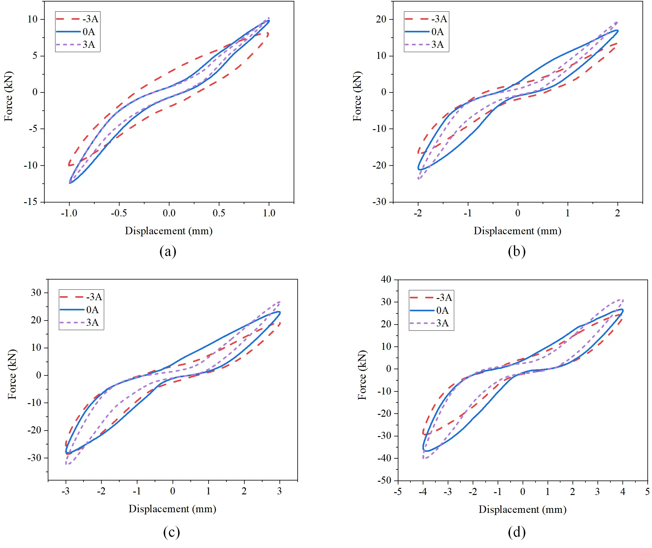
Figure 8. Testing results of the MRF rubber joint. (a) Force-displacement loop under amplitude of 1 mm; (b) Force-displacement loop under amplitude of 2 mm; (c) Force-displacement loop under amplitude of 3 mm; (d) Force-displacement loop under amplitude of 4 mm. MRF: magnetorheological fluid.
As shown in Figure 8a, the minimum output force of the rubber joint occurs at -3 A current. The force gradually increased when changing currents to zero current and positive direction, where the effective stiffness shows an increasing tendency. Notably, the output force at negative current closely approximates that observed at zero current. The sum of the two MRF damping force are larger than the required force of rubber joints during small displacements. Due to the sufficient damping force without power supply to restrict the movement of the rubber layer, the stiffness enhancement effect of applying negative current is limited. For tests with displacement of 2 mm or more, as shown in Figure 8b,c,d, the same performance with changing current is observed. The proposed rubber joint exhibits good variable stiffness effects at different amplitudes. In addition, it can be observed that the applied currents in opposite directions have a more significant stiffness change effect. Due to the insufficient damping force at large amplitude to support the deformation of the top rubber of the damper, there is also a movement during the deformation process. The overall output force is directly related to the damping force, so the control effect in the direction of increasing stiffness will be more significant.
In order to quantitatively compare the variable stiffness effect of rubber joint, the stiffness values under different conditions were calculated and plotted in Figure 9a. The stiffness values for each condition, along with the average stiffness of four displacements, are summarized in Table 3. The stiffness of the rubber joint exhibits a declining trend with increasing displacement, as plotted in Figure 9a. This is attributed to the inability of the dampers’ maximum force to fully constrain the top rubber layer’s deformation during large displacements. Specifically, when the output force of the rubber joint exceeds about 14.96 kN, slippage occurs in the rubber layer, resulting in an overall stiffness lower than that of pure rubber. Therefore, at a displacement of 1 mm, there is almost no difference in stiffness values between the rubber joint in the de-energized state and under negative current. In order to demonstrate this phenomenon more intuitively, the relative change rates of rubber joint under different directions of current were calculated. The relative stiffness enhancement rate is defined as the percentage increase in stiffness under a 3 A current relative to the zero-current state, whereas the reduction rate corresponds to the percentage decrease under a -3 A current. As shown in Figure 9b, the relative stiffness enhancement rate was only 0.89%. When the displacement exceeds 2 mm, the variable stiffness effect under the negative current of the rubber joint will be more obvious, with the relative stiffness enhancement rate exceeding 10% at larger displacement. Consistent with the damper’s principle, the rubber joint exhibits a high average stiffness of 9.16 MN/m in the de-energized state. The average stiffness will increase to 10.16 MN/m when applying a current of 3 A, while it can reduce to about 7.65 MN/m when applying a current of -3 A. The proposed MRF rubber joint exhibits an absolute stiffness changing range of 2.51 MN/m and a stiffness variation capability of nearly 27.4% when compared with the basic stiffness without electricity.
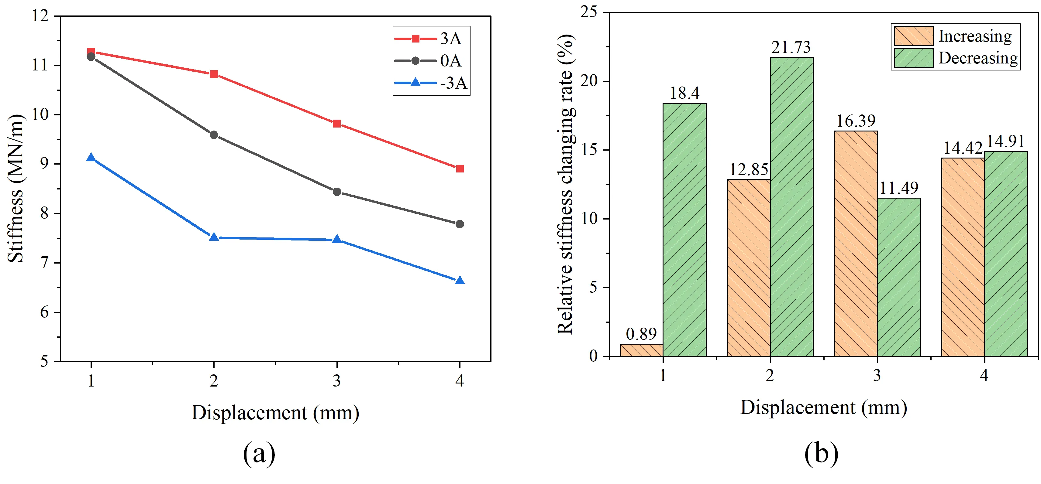
Figure 9. Variable stiffness performance of the MRF rubber joint. (a) Stiffness variation under different displacements and currents; (b) Relative stiffness changing rate of MRF rubber joint. MRF: magnetorheological fluid.
Table 3. Effective stiffness of the MRF rubber joint prototype B.
| Currents | I = 0A | I = 3A | relative enhancement rate | I = -3A | relative reduction rate |
| Stiffness at amplitude of 1 mm (MN/m) | 11.12 | 11.27 | 0.89% | 8.99 | 18.40% |
| Stiffness at amplitude of 2 mm (MN/m) | 9.46 | 10.80 | 12.85% | 7.43 | 21.73% |
| Stiffness at amplitude of 3 mm (MN/m) | 8.35 | 9.76 | 16.39% | 7.44 | 11.49% |
| Stiffness at amplitude of 4 mm (MN/m) | 7.70 | 8.81 | 14.42% | 6.73 | 14.91% |
| Average stiffness (MN/m) | 9.16 | 10.16 | 10.92% | 7.65 | 16.48% |
MRF: magnetorheological fluid.
In addition, in order to evaluate the influence of external excitation frequency on the stiffness of rubber joint, the stiffness characteristics under different frequency excitation were also tested. In the experiments, we selected an excitation amplitude of 3 mm and tested the force-displacement loops at frequencies of 0.5 Hz, 1 Hz, 2 Hz, and 3 Hz, respectively. The results are shown in Figure 10.
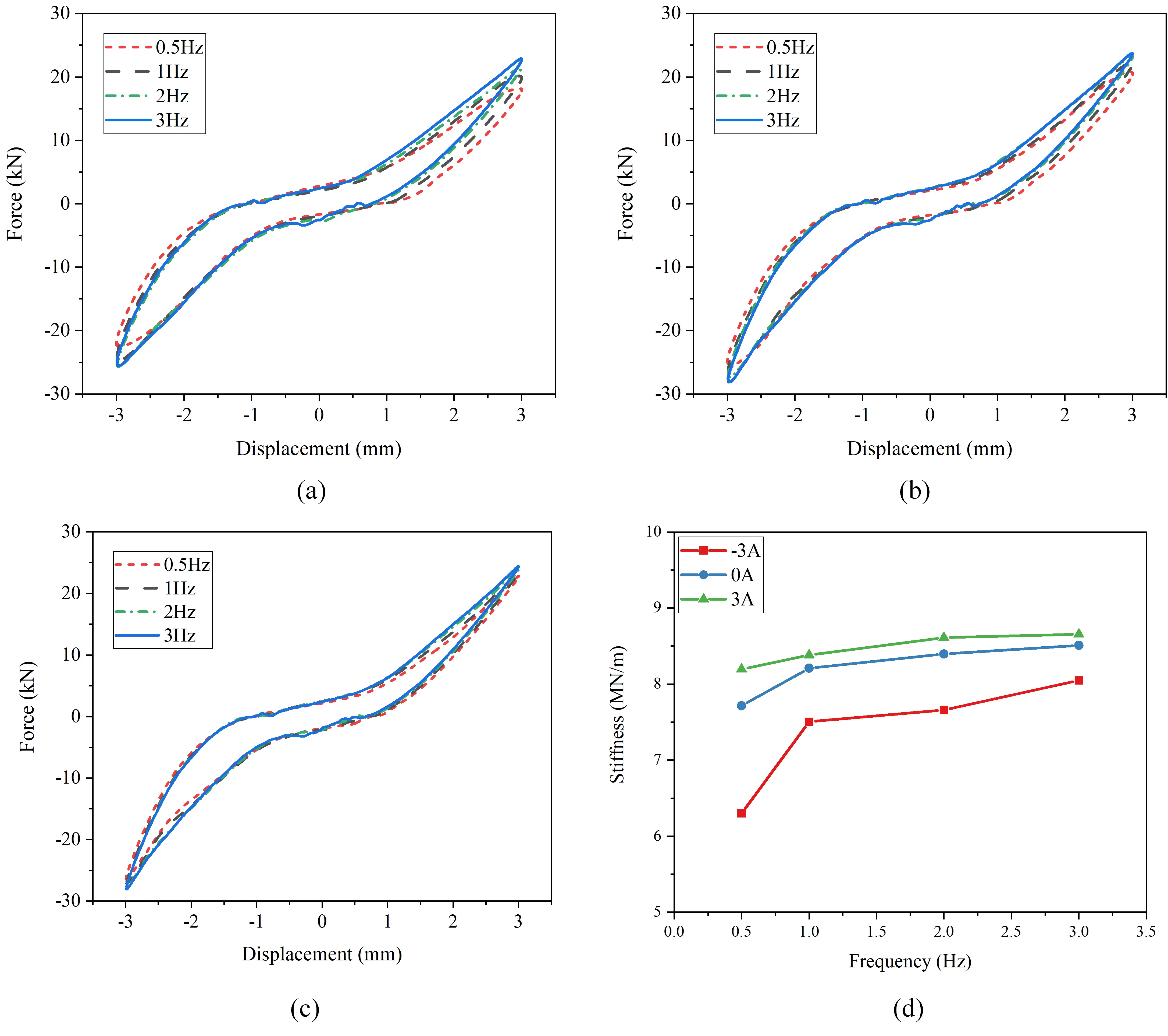
Figure 10. Frequency dependency testing of the MRF rubber joint. (a) Force-displacement loop at current of -3 A; (b) Force-displacement loop at current of 0 A; (c) Force-displacement loop at current of 3 A; (d) Effective stiffness variation with frequency. MRF: magnetorheological fluid.
As shown in Figure 10a, the frequency response of the rubber joint at the minimum stiffness under the corresponding condition of -3 A current is illustrated. It can be seen that as the frequency increases from 0.5 Hz to 3 Hz, the output force of the rubber joint gradually increases, which also means that its stiffness increases accordingly. This indicates that an increase in external excitation frequency will lead to a certain degree of stiffness hardening phenomenon in rubber joint. This is due to the positive correlation between damping force and shear velocity when the damper operates in shear-valve mode. At the same amplitude, a higher excitation frequency also results in a faster shear velocity. This phenomenon is more obvious mainly due to the relatively small basic stiffness of the rubber joint. As shown in Figure 10b,c, the testing results of 0 A and 3 A current for rubber joint also demonstrate a certain degree of stiffness hardening with increasing excitation frequency. The corresponding stiffness values were calculated and plotted as shown in Figure 10d. Under three different currents of 3 A, 0 A and -3 A, the relative stiffness change rates due to frequency increase are 27.8%, 10.3%, and 5.6%, respectively. The stiffness hardening effect of rubber joint diminishes as the baseline stiffness increases. Despite the occurrence of high-frequency stiffness hardening, adjusting the control current has a more pronounced effect on the stiffness change rate than varying the excitation frequency. It can be considered that the proposed rubber joint still exhibits good stiffness variation performance under medium to high frequency excitation conditions.
4. Dynamic and Wheel-Rail Wear Evaluation
Real trains generally require relatively high stiffness of rubber joint, the experimental results show that the proposed rubber joint prototype B can approach this stiffness range. In order to more accurately evaluate the impact of changes in the stiffness on the dynamic performance of trains, the subsequent evaluation was based on the variable stiffness range of rubber joint prototype B with harder stiffness.
The dynamic evaluation in this section is mainly based on the co-simulation of the dynamic software SIMPACK and Simulink. Firstly, we built a train model in SIMPACK software, and the topology diagram of its physical model is shown in Figure 11. The vehicle body model mainly consists of front and rear bogies, 4 wheelsets, and 8 rubber joints. The wheelsets are connected to bogies with primary suspension, while the secondary suspension connects the vehicle body with bogies. According to the motion principle, the vehicle body, bogies, and wheelsets were designated with six DOF. For the rubber joint studied in this article, it is located in the suspension part of the bogie, and the stiffness can be adjusted by applying different currents to regulate the primary suspension stiffness. The main parameters of the train and bogie suspension is given in Table 4. The parameters are selected according to the commercial trains, as listed in this literature[39].
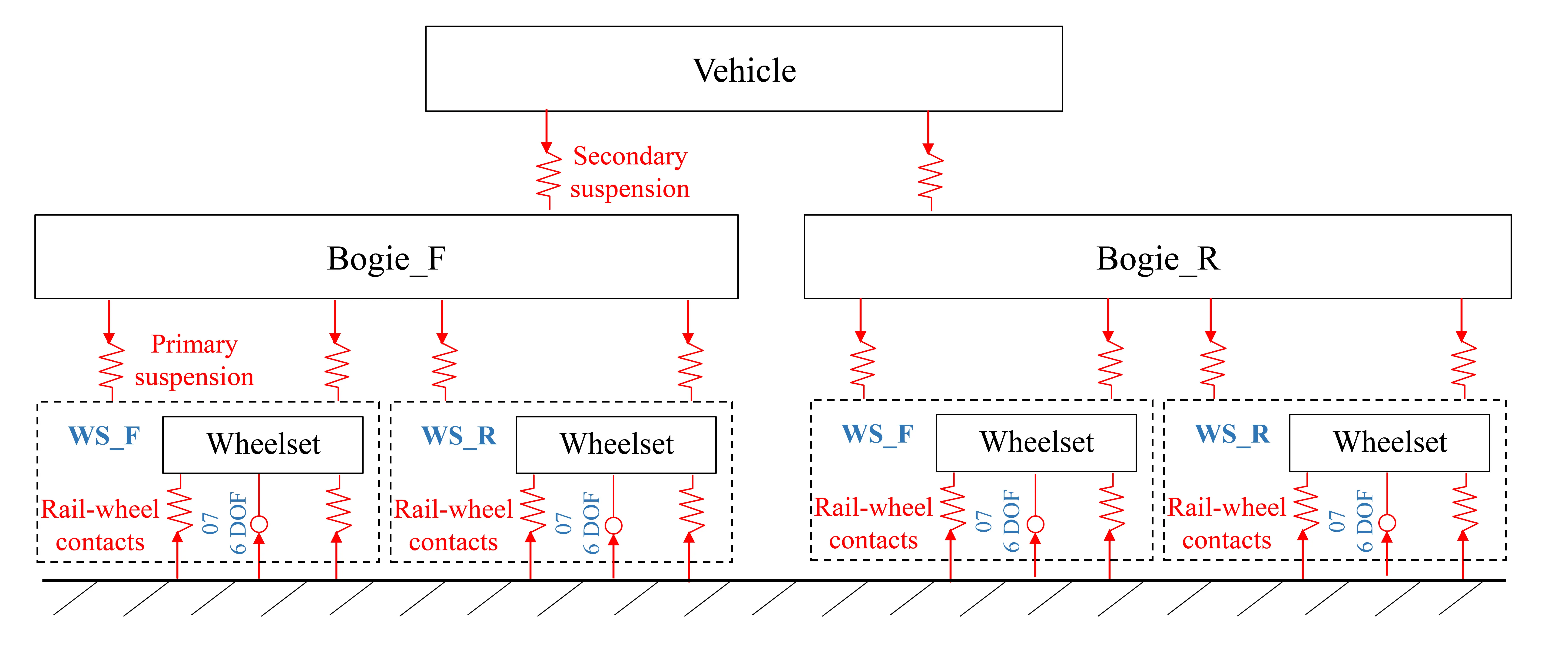
Table 4. Main parameters used in the train model.
| Definition | Parameters | Values |
| Mass of wheelset (kg) | mw | 1,000 |
| Roll moment of inertia of wheelset (kg·m2) | Iwx | 1,000 |
| Pitch moment of inertia of wheelset (kg·m2) | Iwy | 100 |
| Yaw moment of inertia of wheelset (kg·m2) | Iwz | 1,000 |
| Centered wheel rolling radius (m) | r0 | 0.43 |
| Track gauge (m) | a | 1.435 |
| Mass of truck (kg) | mt | 3,000 |
| Roll moment of inertia of truck (kg·m2) | Itx | 2,500 |
| Yaw moment of inertia of truck (kg·m2) | Itz | 1,800 |
| Mass of car body (kg) | mc | 32,000 |
| Primary longitudinal stiffness (MN/m) | Kpx | 7.65-10.16 |
| Primary lateral stiffness (MN/m) | Kpy | 5 |
| Primary vertical stiffness (MN/m) | Kpz | 0.6 |
| Primary vertical damping (Ns/m) | Cpz | 6,000 |
| Secondary longitudinal stiffness (MN/m) | Ksx | 0.15 |
| Secondary lateral stiffness (MN/m) | Ksy | 0.15 |
| Secondary vertical stiffness (MN/m) | Ksz | 0.45 |
| Secondary longitudinal damping (Ns/m) | Csx | 50,000 |
| Secondary lateral damping (Ns/m) | Csy | 50,000 |
| Secondary vertical damping (Ns/m) | Csz | 80,000 |
4.1 Stability evaluation on straight track
The elementary function of the MRF rubber joint should be to ensure sufficient high-speed stability of the train on straight tracks. Critical speed is an important indicator for evaluating the high-speed stability of trains, defined as the threshold speed at which the wheelset appears violent hunting motion. When the train’s running speed exceeds the critical speed, the wheelset’s lateral displacement undergoes sustained lateral oscillations. To simulate the train’s critical speed, a train model was developed using multibody simulation software, and its wheelset lateral displacement was monitored while varying the primary longitudinal stiffness. The track length was set to 5,000 m, with a 10 mm disturbance introduced at 30 m from the starting. The train’s initial speed is 400 km/h and the speed will decrease gradually until the wheelset lateral displacement is stable, so that the critical speed can be obtained.
The simulated wheelset lateral displacement and the critical speed are shown in Figure 12a,b, respectively. By observing the speed points where the lateral displacement of the wheelset diverges, the critical speed at different stiffness can be obtained. The simulation analysis of trains with stiffness of 7.65 MN/m is shown in Figure 12a. It can be seen that the wheelset displacement keeps very stable until it undergoes sustained oscillation when the speed reached about 301.8 km/h. This threshold speed is the critical speed when the primary longitudinal stiffness is minimum. From Figure 12b it can be seen that when the stiffness of MRF rubber joint is increasing, the related threshold speed for oscillation to occur is also increasing. The maximum critical speed will reach about 317.9 km/h when the stiffness is 10.16 MN/m. By increasing the primary longitudinal positioning stiffness of the wheelset within a specific range, the bending motion mode of the wheelset is effectively suppressed. This suppression prevents the development of wheelset hunting motion, thus resulting in an improvement of the system’s critical speed. It is noted that this positive effect exhibits a non-linear relationship with the stiffness value. This demonstrates the ability to further enhance the critical speed of trains by increasing the stiffness of rubber joint.
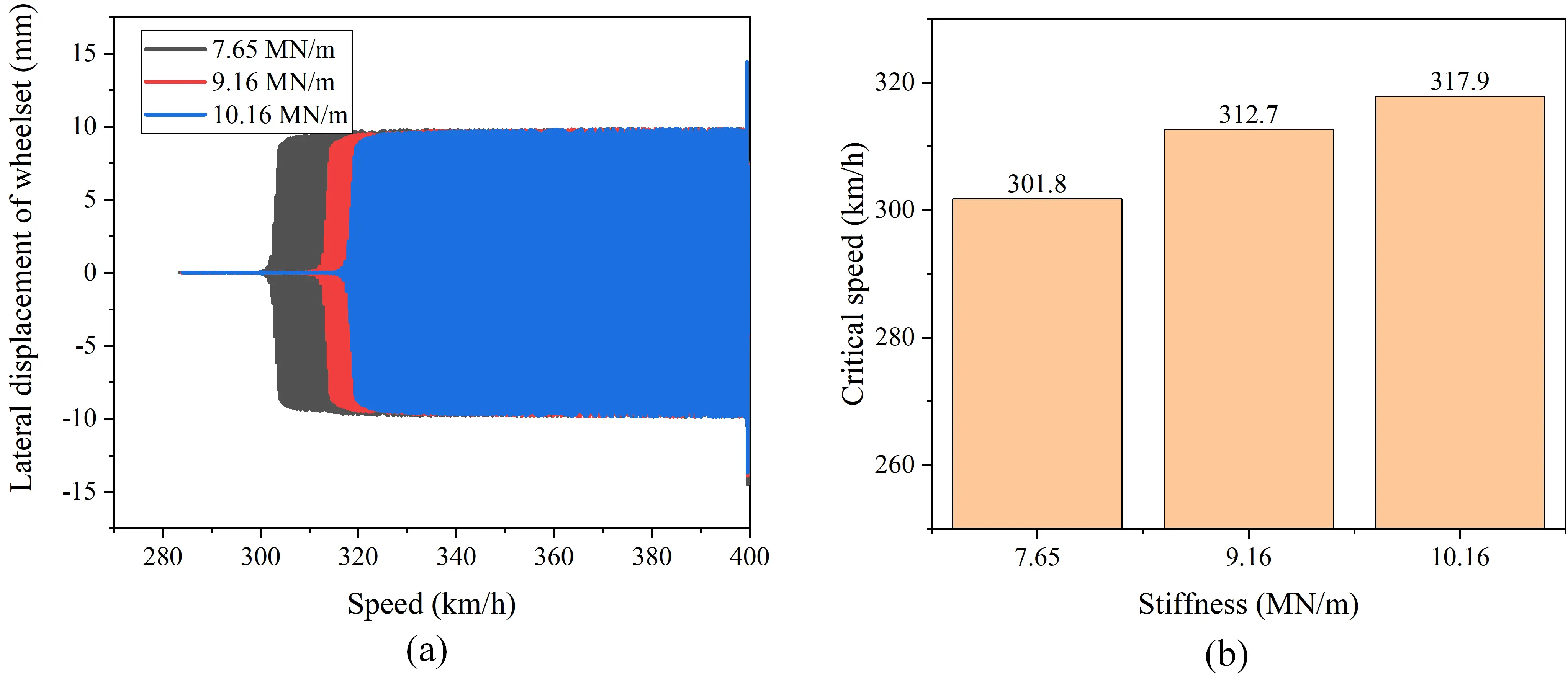
Figure 12. Stability evaluation of the MRF rubber joint on straight track. (a) Wheelset lateral displacement; (b) Critical speed under different stiffness. MRF: magnetorheological fluid.
4.2 Trafficability evaluation on curved track
When a train is running on curved tracks, good curve trafficability is not only closely related to the safety of the train, but also affects the operation and maintenance costs of the vehicle. In order to evaluate the curve trafficability of train with integrated MRF rubber joint, three critical parameters were analyzed, including the wheelset lateral force, derailment coefficient, and wear power. Derailment coefficient is the ratio of the lateral to vertical force at each wheel. Wear power refers to the product of the wear number of wheel-rail contact and running speed, and higher values indicate more severe wheel-rail wear. The simulation was also conducted in multibody simulation software, where a 500 m long curved track with 3,000 m radius and a superelevation of 110 mm is set. In addition, there are a short straight track and transition curved track of 150 m and 480 m, respectively. It was observed that reducing the primary longitudinal stiffness can improve curve trafficability. In this case, the MRF rubber joint is controlled by using positive current to reduce the stiffness. The running speed of the train is 150 km/h. In order to comprehensively analyze the influence of stiffness changes on the curve trafficability of trains, simulations were conducted on the lateral force, derailment coefficient, and wear power of both the left and right wheels of front wheelsets in front bogie. The simulated results are shown in Figure 13.
Figure 13. Curve trafficability evaluation of the MRF rubber joint on curved track. (a) Lateral force of left wheel; (b) Lateral force of right wheel; (c) Derailment coefficient of left wheel; (d) Derailment coefficient of right wheel; (e) Wear power of left wheel; (f) Wear power of right wheel. MRF: magnetorheological fluid.
Figures 13a,b show the lateral forces of the left and right wheels, respectively. When the stiffness is 10.16 MN/m, the lateral force of the left and right wheels can reach around 2,311 N and 1,816 N, respectively. It can be seen from the figures that as the stiffness of the rubber joint decreases, there is a significant reduction in the lateral forces between the wheel-rail contact. Specifically, the minimum lateral force of each wheel gradually decreases to about 1,579 N and 1,379 N, respectively. The average lateral force of left and right wheels has decreased by about 28.4% compared to the maximum force. As can be seen in Figure 13c,d, the average derailment coefficient of two wheels is about 0.039 when the stiffness reaches 10.16 MN/m. Simultaneously, the derailment coefficient gradually decreases to about 0.028 when the stiffness is 7.65 MN/m. This reduction indicates an improvement in operational safety as a result of stiffness control. To evaluate the wear condition of the train, the average wear power of the two wheelsets is compared. As shown in Figure 13e,f, it can be seen that as the stiffness of the rubber joint decreases, the wear power of the left and right wheels gradually decreases. It should be noted that due to the right-hand curvature of the simulated track, the train experiences centrifugal forces that cause it to shift toward the outer rail, which is the left side. Therefore, the left wheel will be subjected to resulting in significantly higher wear power than that of the right wheel. The average wear power of two wheels is reduced from 224.3 W to 159.4 W, with a reduction rate of 28.9%, respectively. Simulation results indicate that reducing the primary longitudinal suspension stiffness enhances the train’s curve-negotiation performance. A lower stiffness allows the wheelset to better align with the track curvature, resulting in reduced wheel-rail contact forces and consequently lower wear. This improvement not only ensures operational safety but also reduces long-term maintenance costs.
4.3 Control algorithm and simulated results
In order to more systematically evaluate the performance of variable stiffness MRF rubber joints, a simple control strategy is proposed based on track curvature identification and its control effect is simulated using a co-simulation environment based on multibody simulation software and Simulink software. In this co-simulation, the same track compromising both straight and curved segments described in Section 4.2 was employed. To achieve a more realistic simulation effect, lateral track irregularity is also introduced in track excitation. The framework of the co-simulation is shown in Figure 14. In the co-simulation, the basic principle is to evaluate the train’s condition on the track and dynamically adjust the stiffness of the MRF rubber joints to meet the actual physical boundary conditions. Specifically, the track curvature identification is achieved by measuring train’s yaw angle. The yaw angular velocity is calculated to determine whether the train is running on a straight track or a curved track. The multibody simulation software mainly outputs the yaw angle of the train body and receives the stiffness values of MRF rubber joints calculated by Simulink.
The control algorithm is illustrated in a flowchart in Figure 15. Firstly, the change rate of yaw angle of train body is calculated to determine whether the train is running on a straight or a curved track. When the train runs on a curved track, the yaw angle will change significantly, whereas during straight-track running, only minor fluctuations are observed. Based on this observation, the yaw angular velocity threshold athreshold is set to 0.001 rad/s. Secondly, a stiffness increment related to the rate of change of the yaw angle is calculated to determine the specific amount by which the stiffness of rubber joint is increased or decreased. The stiffness of the rubber joint will increase on straight roads to enhance high-speed stability, and decrease on curves to improve curve trafficability. The typical state of MRF rubber joint is utilizing without any power supply, so this step is used to calculate the absolute change value. The calculated stiffness of MRF rubber joint kc can be expressed as:
Where
Table 5. Main parameters used in the co-simulation.
| Definition | Parameters | Values |
| Threshold of yaw angular velocity (rad/s) | athreshold | 0.001 |
| Stiffness gain factor on curved track (N/m)/(rad/s) | Gain1 | 300,000 |
| Stiffness gain factor on straight track (N/m)/(rad/s) | Gain2 | 1,000,000 |
| The initial longitudinal stiffness (N/m) | k0 | 9,160,000 |
| The maximum longitudinal stiffness (N/m) | kmax | 10,160,000 |
| The minimum longitudinal stiffness (N/m) | kmin | 7,650,000 |
The train dynamics co-simulation results with and without the control algorithm are shown in Figure 16. The lateral acceleration of train body is displayed in Figure 16a. It can be seen that the train body has a huge oscillation when it passed through the curved track. Due to the control algorithm, the lateral acceleration was reduced, indicating an improvement in ride comfort. According to the testing results, the root mean square (RMS) value of the lateral acceleration was reduced from 0.198 m/s2 to 0.156 m/s2, which has a relative change rate of 21.2%. As it can be seen from Figure 16b, the wear number of wheel-rail was also reduced when running with the control algorithm. The RMS value of wear power decreased from 246.1 W to 179.9 W, which has a relative change rate of 26.9%. It can be seen that the control strategy is more effective on curved tracks, stemming primarily from the asymmetric impact of increasing stiffness in the positive direction and decreasing stiffness in the negative direction of the rubber joint proposed in this work. When running in a straight line, it maintains a relatively stable state, with no significant changes in acceleration and wear. However, during curved tracks, the stiffness of rubber joint can be reduced even lower, allowing better adaption to track curvature and substantially reducing wheel-rail wear. At the same time, the wheel rail excitation reduces the lateral vibration acceleration transmitted to the vehicle body due to the softer connection. The co-simulation verified that the MRF rubber joint combined with the proposed algorithm are effective to reduce the wear of wheel-rail contact and enhance its comfort.
Figure 16. The performance of train with control algorithm. (a) Lateral acceleration of the train body; (b) Wear power of wheel-rail.
5. Conclusion
This study proposed an MRF rubber joint with bidirectional adjustable stiffness to reduce wheel wear and enhance safety of high-speed trains. The new structure incorporates MRF dampers energized by permanent magnetic and electromagnetic field to achieve controllable stiffness, which can ensure fail-safe operation while expanding the adjustable force range. Then, the experimental tests on MTS machines verify that the damper can adjust the damping force for about 18.2 times. Furthermore, two types of rubber joints with softer and harder basic stiffness are experimentally verified, which exhibit relative stiffness variation rates of about 160.1% and 27.4%, respectively. Finally, the simulation results based on harder stiffness suitable for vehicles, show that adjusting the primary longitudinal stiffness can improve both high-speed stability and curve-negotiation performance. Additionally, a track curvature-based control algorithm is proposed and validated through co-simulation, resulting in a 21.2% reduction in lateral acceleration and a 26.9% decrease in wheel-rail wear. The proposed MRF rubber joint shows the potential to reduce the wear and enhance the safety of high-speed trains.
Authors contribution
Gong N: Writing-original draft, data analysis, investigation, visualization, conceptualization.
Yang J: Writing-review & editing, data analysis, visualization.
Li W: Methodology, supervision.
Sun S: Writing-review & editing, data analysis, supervision, funding acquisition.
Conflicts of interest
Weihua Li is an Associate Editor of Smart Materials and Devices, and Shuaishuai Sun is a member of the Youth Editorial Board of Smart Materials and Devices. The other authors declare no conflicts of interest.
Ethical approval
Not applicable.
Consent to participate
Not applicable.
Consent for publication
Not applicable.
Availability of data and materials
Not applicable.
Funding
This research is supported by the National Natural Science Foundation of China (Grant No. 52005474, 52105081), Major Project of Anhui Province’s Science and Technology Innovation Breakthrough Plan (202423h08050003), USTC start-up funding (KY2090000067) and the Fundamental Research Funds for the Central Universities (WK2480000009).
Copyright
© The Author(s) 2025.
References
-
1. Strano S, Terzo M, Tordela C. Output-only estimation of lateral wheel-rail contact forces and track irregularities. Veh Syst Dyn. 2024;62(10):2481-2509.[DOI]
-
2. Choi HY, Lee DH, Song CY, Lee J. Optimization of rail profile to reduce wear on curved track. Int J Precis Eng Manuf. 2013;14(4):619-625.[DOI]
-
3. Wang M, Jia S, Chen E, Yang S, Liu P, Qi Z. Research and application of neural network for tread wear prediction and optimization. Mech Syst Signal Process. 2022;162:108070.[DOI]
-
4. Yang Y, Ling L, Wang J, Zhai , W . A numerical study on tread wear and fatigue damage of railway wheels subjected to anti-slip control. Friction. 2023;11(8):1470-1492.[DOI]
-
5. Li Y, Ren Z, Enblom R, Stichel S, Li G. Wheel wear prediction on a high-speed train in China. Veh Syst Dyn. 2020;58(12):1839-1858.[DOI]
-
6. Ye Y, Sun Y, Dongfang S, Shi D, Hecht M. Optimizing wheel profiles and suspensions for railway vehicles operating on specific lines to reduce wheel wear: A case study. Multibody Syst Dyn. 2021;51(1):91-122.[DOI]
-
7. Farhat N, Ward CP, Goodall RM, Dixon R. The benefits of mechatronically-guided railway vehicles: A multi-body physics simulation study. Mechatronics. 2018;51:115-126.[DOI]
-
8. Ji Y, Ren L, Huang Y. Passive radial mechanism of a bogie with the auxiliary steering device for the straddle monorail vehicle. Veh Syst Dyn. 2021;59(9):1418-1442.[DOI]
-
9. Tian S, Luo X, Xiao C, Leng H, Zhou J. Distribution Method of Active Steering Control for Rail Vehicles Based on Overdrive Characteristics. IEEE Trans Veh Technol. 2023;72(12):15634-15647.[DOI]
-
10. Kalivoda J, Bauer P, Novák Z. Assessment of active wheelset steering system using computer simulations and roller rig tests. Appl Sci. 2021;11(24):11727.[DOI]
-
11. Cheng J, Yan H, Zhang X, Chen K, Yao Y. HIL simulation of high-speed train active stability employing active inertial actuators. Veh Syst Dyn. 2023;61(11):2848-2866.[DOI]
-
12. Shi X, Zhu S, Ni YQ, Li J. Vibration suppression in high-speed trains with negative stiffness dampers. Smart Struct Syst. 2018;21(5):653-668.[DOI]
-
13. Xu Q, Tan Z, Wang H. Global existence and asymptotic behavior for the 3D compressible magneto-micropolar fluids in a bounded domain. J Math Phys. 2020;61(1):011506.[DOI]
-
14. Yang C, Xu N, Wang W, Li W, Ren Z. Self-steering performance of a new bogie with four independently rotating wheels using caster angle. Int J Rail Transp. 2024;12(3):476-491.[DOI]
-
15. Luo R, Liu C. Dynamics simulation of the high-speed train using interconnected hydro-pneumatic suspension as a self-steering system. Veh Syst Dyn. 2022;60(6):2055-2074.[DOI]
-
16. Stichel S, Persson R, Giossi R. Improving rail vehicle dynamic performance with active suspension. High-speed Railw. 2023;1(1):23-30.[DOI]
-
17. Hur H, Moon K, Seo J, Choi J, Lee J. Wheel noise reduction performance of active steering bogie in curved section. J Mech Sci Technol. 2024;38(9):4733-4741.[DOI]
-
18. Fu B, Bruni S. Fault-tolerant design and evaluation for a railway bogie active steering system. Veh Syst Dyn. 2022;60(3):810-834.[DOI]
-
19. Yuan L, Pan Z, Ding D, He F, van Duin S, Li H, et al. Investigation of humping pheomenon for the multi-directional robotic wire and arc additive manufacturing. Robot Comput-Integr Manuf. 2020;63:101916.[DOI]
-
20. Nguyen SD, Choi SB, Nguyen QH. A new fuzzy-disturbance observer-enhanced sliding controller for vibration control of a train-car suspension with magneto-rheological dampers. Mech Syst Signal Process. 2018;105:447-466.[DOI]
-
21. Yu J, Dong X, Wang T, Zhou Z, Zhou Y. Damping characteristics of a magneto-rheological damper with dual independent controllable ducts. J Intell Mater Syst Struct. 2022;33(2):365-376.[DOI]
-
22. Hu G, Ying S, Qi H, Yu L, Li G. Design, analysis and optimization of a hybrid fluid flow magnetorheological damper based on multiphysics coupling model. Mech Syst Signal Process. 2023;205(1):110877.[DOI]
-
23. Chen G, Xiong X, Lou Y, Li Z. Modeling and observation of rate-dependent hysteresis and creep phenomena in magnetorheological clutch. IEEE/ASME Trans Mechatron. 2022;27(4):2053-2061.[DOI]
-
24. Wu J, Deng B, Huang Y, Zhang H, Tang S. A multi-pole magnetorheological clutch powered by permanent magnets and excitation coils. J Intell Mater Syst Struct. 2023;34(2):217-228.[DOI]
-
25. Leng D, Feng W, Ning D, Liu G. Analysis and design of a semi-active X-structured vibration isolator with magnetorheological elastomers. Mech Syst Signal Process. 2022;181(1-2):109492.[DOI]
-
26. Yang J, Du H, Li W, Li Y, Li J, Sun S, et al. Experimental study and modeling of a novel magnetorheological elastomer isolator. Smart Mater Struct. 2013;22(11):117001.[DOI]
-
27. Liao WH, Wang DH. Semiactive vibration control of train suspension systems via magnetorheological dampers. J Intell Mater Syst Struct. 2003;14(3):161-172.[DOI]
-
28. Oh JS, Shin YJ, Koo HW, Kim HC, Park J, Choi SB. Vibration control of a semi-active railway vehicle suspension with magneto-rheological dampers. Adv Mech Eng. 2016;8(4):1-13.[DOI]
-
29. Liao Y, Liu Y, Yang S. Semiactive control of high-speed railway vehicle suspension systems with magnetorheological dampers. Shock Vib. 2019;2019(1):1-17.[DOI]
-
30. Ha SH, Choi SB, Lee GS, Yoo WH. Control performance evaluation of railway vehicle MR suspension using fuzzy sky-ground hook control algorithm. J Phys Conf Ser. 2013;412(1):2042.[DOI]
-
31. Zong LH, Gong XL, Xuan SH, Guo CY. Semiactive control of high-speed railway vehicle suspension with magnetorheological dampers. Veh Syst Dyn. 2013;51(5):600-626.[DOI]
-
32. Shin YJ, You WH, Hur HM, Park JH, Lee GS. Improvement of ride quality of railway vehicle by semiactive secondary suspension system on roller rig using magnetorheological damper. Adv Mech Eng. 2014;6:298382.[DOI]
-
33. Shin Y, Ahn D. Design and analysis of variable stiffness joint for railway vehicles using magneto-rheological elastomer. J Korean Soc Precis Eng. 2021;38(2):131-137.[DOI]
-
34. Yang J, Sun S, Guo N, Ning D, Nakano M, Li Z, et al. Development of a smart rubber joint for train using shear thickening fluids. Smart Mater Struct. 2020;29(5):055036.[DOI]
-
35. Harris BJ, Sun SS, Li WH. Improving stability and curving passing performance for railway vehicles with a variable stiffness MRF rubber joint. Smart Mater Struct. 2017;26(3):035055.[DOI]
-
36. Sun S, Yang J, Du H, Li W. Overcoming the conflict requirement between high-speed stability and curving trafficability of the train using an innovative magnetorheological elastomer rubber joint. J Intell Mater Sys Struct. 2018;29(2):214-222.[DOI]
-
37. Yang Y, Zeng W, Wang T, Liao Y. Multi-objective optimization of suspension parameters for rail vehicles based on a virtual prototype surrogate model. J Chin Inst Eng. 2016;39(6):746-754.[DOI]
-
38. Zhou G, Mi X, Zhang H, Liao D, Wu K. Nonlinear finite element analysis and experimental study on the stiffness of rubber joint. J Chin Inst Eng. 2020;43(7):603-612.[DOI]
-
39. Zhou SX, Tao YZ, Zhang ZH, Yang JZ. Example tutorial for SIMPACK 9. 1th ed. Beijing: Beijing United Publishing; 2013.
Copyright
© The Author(s) 2025. This is an Open Access article licensed under a Creative Commons Attribution 4.0 International License (https://creativecommons.org/licenses/by/4.0/), which permits unrestricted use, sharing, adaptation, distribution and reproduction in any medium or format, for any purpose, even commercially, as long as you give appropriate credit to the original author(s) and the source, provide a link to the Creative Commons license, and indicate if changes were made.
Publisher’s Note
Science Exploration remains a neutral stance on jurisdictional claims in published
maps
and institutional affiliations. The views expressed in this article are solely those
of
the author(s) and do not reflect the opinions of the Editors or the publisher.
Share And Cite


Science Exploration Style
Gong N, Yang J, Li W, Sun S. Investigation of wheel-rail wear reduction by using MRF rubber joints with bidirectional adjustable stiffness. Smart Mater Devices. 2025;1:202530. https://doi.org/10.70401/smd.2025.0018
Tips
Copy completed.
Submit a Manuscript
Author Instructions
Cite this Article
Article Metrics
0
View
0
Download
0
Cited
Article Updates

- Abstract
- Keywords
- 1. Introduction
- 2. Structural Design of MRF Rubber Joint
- 3. Experimental Characterization
- 4. Dynamic and Wheel-Rail Wear Evaluation
- 5. Conclusion
- Authors contribution
- Conflicts of interest
- Ethical approval
- Consent to participate
- Consent for publication
- Availability of data and materials
- Funding
- Copyright
Science Exploration Style
Gong N, Yang J, Li W, Sun S. Investigation of wheel-rail wear reduction by using MRF rubber joints with bidirectional adjustable stiffness. Smart Mater Devices. 2025;1:202530. https://doi.org/10.70401/smd.2025.0018
copy