A self-sensing friction damper with energy dissipation and sensing characteristics
Ning Ma
1

,
Hang Ming
1
,
Shichao Zhang
1
,
Linpei Zhou
1
,
Chi Zhang
2,*
,
Xufeng Dong
3,*
*Correspondence to:
Chi Zhang, Beijing Key Laboratory of Micro-Nano Energy and Sensor, Center for High-Entropy Energy and Systems, Beijing Institute of Nanoenergy and Nanosystems, Chinese Academy of Sciences, Beijing 100000, China.
E-mail: czhang@binn.cas.cn
Xufeng Dong, School of Materials Science and Engineering, Dalian University of Technology, Dalian 116024, Liaoning, China. E-mail: dongxf@dlut.edu.cn
Xufeng Dong, School of Materials Science and Engineering, Dalian University of Technology, Dalian 116024, Liaoning, China. E-mail: dongxf@dlut.edu.cn
Smart Mater Devices. 2026;2:202610. 10.70401/smd.2026.0031
Received: February 27, 2026Accepted: April 01, 2026Published: April 03, 2026
Abstract
Friction dampers dissipate seismic energy through sliding but lack self-sensing capability. This study integrates friction dampers with triboelectric nanogenerators (TENGs), which convert mechanical energy into electrical signals, creating a self-sensing damper. Using friction pairs with large triboelectric differences, the system simultaneously achieves energy dissipation and sensing. During sliding, mechanical energy is partially converted into heat (dissipation) and electricity (sensing). Theoretical models link displacement and velocity to voltage and current, validated through cyclic loading tests varying velocity, displacement, and friction force. Results show stable energy dissipation (300-770 J/cycle) comparable to conventional dampers. Sensing performance is strong: voltage correlates linearly with displacement (0.00526 V/mm, R2 = 0.94), and current with velocity (0.01914 μA/(mm/s), R2 > 0.99). Unlike conventional TENGs, high friction alters triboelectric behavior via wear and heating, producing a unique voltage-velocity relationship. Scanning electron microscopy analysis confirms maximum wear at 34.2 kN, aligning with inflection points in electrical response. An empirical Q-V-f formula for high-friction conditions enriches triboelectric theory and guides damper design, emphasizing friction optimization for balanced dissipation and sensing stability.
Keywords
Friction dampers, self-sensing, triboelectric nanogenerator, energy dissipation, sensing performance
1. Introduction
Dampers can be categorized into rate-dependent and displacement-dependent types based on their energy dissipation mechanisms[1-7]. Once the preset limit working velocity of rate-dependent dampers or the limit displacement of displacement-dependent dampers is exceeded, damper failure will occur, endangering the safety of engineering structures. Therefore, real-time monitoring of the damper’s working state and the vibration response of energy dissipation and vibration reduction structures is essential.
Installing separate structural health monitoring systems for energy dissipation systems increases system complexity and costs. Empowering dampers with self-sensing capabilities offers a viable solution. Self-sensing dampers can maintain their original energy dissipation and vibration reduction functions while monitoring their working conditions, enabling structural safety assessment. This integration represents an inevitable development for combining structural energy dissipation, vibration reduction, and health monitoring systems.
In recent years, numerous scholars have delved into self-sensing damper research[8-12]. Yuan et al. integrated fiber optic sensors with viscous dampers, creating a viscous damper with adjustable damping force and velocity measurement functions[13]. Lam et al. added displacement and speed sensors to ordinary magnetorheological dampers, developing an intelligent magnetorheological damper with a monitoring system[14]. However, these self-sensing dampers merely relocate sensors from the structure to the damper. The sensing and energy dissipation elements remain independent, and additional power supply and complex signal acquisition equipment are required, increasing costs and reducing reliability. The key bottleneck restricting self-sensing damper development is endowing them with self-sensing functions without extra sensing units and minimizing external energy dependence.
Friction dampers, widely used displacement energy dissipators, convert mechanical energy into heat through sliding friction work[15]. Such dampers feature excellent energy dissipation, stable performance, durability, and are less affected by temperature. Their simple structure, accessible materials, and low cost make them popular in structural vibration reduction systems, especially for controlling the near-fault seismic response of structures and the seismic response of medium and high-rise buildings[16-21]. Real-time collection of parameters such as displacement, velocity, and acceleration of the sliding friction mechanism in friction dampers can enable self-state perception during energy dissipation and overall structural safety monitoring.
Friction can generate both heat and electricity. The triboelectric nanogenerator (TENG), proposed by Wang’s group in 2012[22], operates on the principles of contact electrification and electrostatic induction, converting mechanical energy into electrical energy. With four working modes[23-28], TENG can be used for energy harvesting and sensing mechanical motion signals. Although TENG-based self-powered sensors have been extensively studied in fields such as wearable electronics and micro-energy harvesting[29-32], their application in civil engineering remains extremely rare. This is primarily because existing TENG sensors are designed for low-friction, small-displacement, low-load scenarios, which are fundamentally different from the high-friction, large-displacement, high-load conditions typical of civil engineering structures. The relative sliding motion of friction dampers aligns with the horizontal sliding mode of TENG, suggesting the potential for organic integration by replacing friction materials.
To address the aforementioned challenges and bridge the gap between TENG technology and civil engineering applications, this study proposes a self-sensing plate-type friction damper that integrates a sliding-mode TENG. By selecting friction materials with distinct charge affinities, the device achieves dual functionality: energy dissipation through sliding friction and self-driven sensing via triboelectrification. The key innovation lies in adapting TENG to operate under the high-friction, large-displacement conditions typical of civil engineering structures, a scenario fundamentally different from the low-friction environments where TENG sensors are conventionally applied. Specifically, this work: (1) establishes the physical relationship between mechanical motion and electrical output under high-friction conditions; (2) proposes a design theory for the integrated energy dissipation and sensing system; and (3) experimentally validates the self-sensing performance through a custom-built test system, with particular focus on the influence of friction force on sensing accuracy[33]. This integration not only eliminates the need for separate sensors and external power supplies but also provides a new pathway for real-time structural health monitoring in seismic-prone regions.
2. Structural Design of Self-Sensing Friction Damper
2.1 Structural design of self-sensing damper
Friction dampers require materials resistant to high friction, pressure, and wear, typically metals (e.g., copper, steel, alloys). However, homogeneous metals fail to meet triboelectrification requirements for TENGs. For the self-sensing damper, friction pair materials must balance energy dissipation (high friction coefficient, durability) and triboelectrification (significant polarity difference). Among tested materials, steel-PTFE exhibits a kinetic friction coefficient of 0.05, and steel-polyvinyl chloride (PVC) 0.40. Considering both energy dissipation and sensing performance, PVC (strong negative polarity) and steel (positive electrode) were selected as friction pairs, operating in single-electrode horizontal sliding mode. The structure retains a traditional steel plate on one side and a PVC plate on the other, with a grounded layer and insulating layer on the back (Figure 1).
Detailed dimensions are provided in Figure S1. The damper features a load-bearing frame with one sliding main plate and two sliding sub-plates, comprising 2 pieces of 3 mm-thick steel plates, 2 pieces of 2 mm-thick PVC plates, 4 pieces of 1 mm-thick conductive copper plates, and 2 pieces of 1 mm-thick insulating rubber plates. The insulating rubber is a commercially available high-voltage rubber sheet with a service temperature range of -60 °C to 200 °C. Wires connected to copper plates measure charge, voltage, and current. Fixing clamps are at both ends, with 20 mm grade 10.9 high-strength bolts applying prestress. A 160 mm × 32 mm slot in the main plate allows a maximum 20 mm stroke. To avoid bolt shear failure from longitudinal eccentricity (which causes slot wall-bolt contact), the slot width (32 mm) leaves 6 mm clearance on each side of the bolt shank. All plates have bolt holes matching the high-strength bolts. Steel main/sub-plates provide uniform pressure; insulating rubber layers on the main plate prevent charge leakage, with 1 mm copper plates attached externally. The copper plate and 3 mm stainless steel friction plate are bonded with insulating paint (applied 2-3 times, conductivity verified via a multimeter) to form the negative electrode. The PVC positive electrode is assembled symmetrically, with sliding sub-plates as the outer layer. Friction force (f) is adjusted by varying bolt torque to control positive pressure (F), given f = kF (k = the friction coefficient). The damper’s maximum designed output is 50 kN; safety verification of critical sections and bolts confirms it meets load-bearing requirements.
2.2 Energy dissipation mechanism of self-sensing friction damper
The structure of the friction damper from the exterior to the interior consists of a cover plate, a channel bracing member, and a gusset plate. After applying a preload to the bolt, the friction damper creates a positive pressure between the cover plate and the gusset plate and dissipates energy through the relative movement between them. The magnitude of the sliding friction force is controlled by factors such as the number of friction surfaces, the properties of the friction material, and the applied preload.
2.3 Sensing mechanism of self-sensing friction damper
The mechanical energy generated by the vibration of building structures can not only be dissipated as internal energy through frictional heat generation by the friction damper but also, by choosing materials with significant differences in electrode polarity as friction pairs and utilizing the triboelectric effect, a portion of the mechanical energy can be simultaneously converted into electrical energy. The self-sensing principle is shown in Figure 2. When there is a relative displacement between the friction main plate and the friction sub-plates, by detecting electrical signals such as voltage (V) and current (I) between the positive triboelectric plate and the negative triboelectric plate, the relative displacement (x), velocity (v), and other mechanical motion signals of the sliding friction components can be monitored in real time.
The V-Q-x relationship of the attached electrode sliding TENG can be obtained as:
where C is capacitance, Q is transferred charge, VOC is the open-circuit voltage, w is plate width, ε0 is vacuum dielectric constant, l is plate length, σ is surface charge density, d0 is effective thickness constant.
To obtain the short-circuit current ISC, substituting V = 0 into the equation (1), we can obtain the short-circuit charge as follows.
According to equation (1), the short-circuit current ISC is given below.
By making use of the proportional relationship between current, voltage, and displacement as well as velocity of the attached electrode sliding TENG, the mechanical stimulus of a building can be transformed into electrical signals, thereby realizing the monitoring and sensing of the operation of the friction damper.
The self-sensing mechanism relies on the single-electrode horizontal sliding mode of TENG. Initially, the dielectric and metal plate are in close contact; their differing electron affinity induces negative charges on the dielectric and equal positive charges on the metal via triboelectrification. The dielectric’s insulation prevents charge leakage, and bolt-induced pressure minimizes the distance between charged surfaces, resulting in negligible potential difference. When the positively charged upper plate slides outward, reduced contact area separates in-plane charges, raising the upper plate’s potential. This drives electrons from ground to the lower electrode to balance the potential difference, with transferred charges approximating separated charges during sliding, causing continuous charge flow until motion stops or reverses. Upon sliding back, the dielectric’s insulation prevents charge annihilation. Increased contact area forces excess charges to flow back to ground through the external load, maintaining electrostatic equilibrium.
3. Experimental Setup and Methodology
3.1 Experimental design
Damper friction force was controlled via bolt torque. To investigate the effects of velocity, displacement, and friction force on sensing performance and energy dissipation, tests were conducted under variable conditions (Table 1) using a controlled-variable approach: (1) fixed friction force and displacement to isolate the velocity effects; (2) fixed velocity and friction force to isolate the displacement effects; (3) fixed velocity and displacement to isolate the friction force effects.
Table 1. Test condition.
| Number | Research parameter | Maximum separation displacement x (mm) | Average velocity v (mm/s) | Friction force F (kN) |
| 1 | velocity | 16 | 2 | 22 |
| 2 | 16 | 4 | 22 | |
| 3 | 16 | 6 | 22 | |
| 4 | 16 | 8 | 22 | |
| 5 | 16 | 10 | 22 | |
| 6 | displacement | 8 | 6 | 22 |
| 7 | 10 | 6 | 22 | |
| 8 | 12 | 6 | 22 | |
| 9 | 14 | 6 | 22 | |
| 10 | 16 | 6 | 22 | |
| 11 | friction force | 16 | 6 | 27.4 |
| 12 | 16 | 6 | 29.3 | |
| 13 | 16 | 6 | 30.8 | |
| 14 | 16 | 6 | 32.6 | |
| 15 | 16 | 6 | 34.2 | |
| 16 | 16 | 6 | 35.8 | |
| 17 | 16 | 6 | 37.1 |
3.2 Experimental platform
Experiments were performed with a Material Testing Systems (MTS) Landmark 250 kN fatigue testing machine with triangular wave cyclic loading. Since the MTS equipment itself has an independent grounding protection, the entire structure is stably grounded through the testing machine. Measured parameters included displacement (x, via linear variable differential transformer, defined as the gap between sliding main and sub-plates), open-circuit voltage (V), short-circuit current (I), and sliding friction force (f, via the machine’s chuck force sensor). Electrical signals (V, I, charge) were acquired using an NI-9215 module, NI-cDAQ9174 chassis, and Keithley 6514 electrometer, with data logged via LabVIEW (Figure 3). The Keithley 6514 electrometer features an input impedance greater than 200 × 1012 Ω in voltage measurement mode and an input voltage drop of less than 20 μV. Therefore, no external shunt resistor was required for current measurement, as the electrometer itself provides the necessary high-impedance interface. Bolt torque was precisely adjusted using a torque wrench.
Figure 3. Layout diagram of electrical and mechanical experimental platform. MTS: MTS Systems Corporation; LVDT: linear variable differential transformer.
Unlike conventional TENGs with negligible friction, the proposed damper operates under high friction, introducing thermal effects and surface wear that may alter sensing behavior. Thus, an infrared thermal imager monitored temperature variations, and new friction plates were used for each friction force adjustment. Post-test, scanning electron microscopy (SEM) analyzed surface morphology changes.
4. Energy Dissipation Properties of Self-Sensing Friction Damper
For the first set of test conditions in Table 1, under identical friction force and displacement conditions, the hysteresis curves of the self-sensing friction damper at various velocities are presented in Figure 4a,b,c,d,e. It should be noted that the negative separation displacement of the self-sensing friction damper does not reach the target value. This is partly because redundancy is provided for both the bolt hole and the chuck in the design to prevent structural damage during the experiment. Additionally, it is due to errors in processing and installation. Each working condition undergoes six cycles, and the hysteresis curves for each cycle are nearly identical, suggesting that the energy dissipation performance of the self-sensing friction damper is stable. By comparing the hysteresis curves at different velocities, it can be observed that the maximum output of the damper changes only slightly. The hysteresis curves under various working conditions exhibit a “trapezoidal” shape with a large left side and a small right side, indicating that the friction force changes during the separation process of the friction components. This phenomenon is due to the fact that the limit bolts of the plate friction damper should be evenly distributed on the damper. However, the bolts of the damper designed in this paper are unevenly distributed, resulting in uneven pressure distribution. The energy dissipation of the damper is obtained by integrating the closed area of the single-cycle hysteresis curve. As shown in Figure 4f, it can be seen that at different velocities, the energy dissipation of the damper does not change significantly. The single-cycle energy dissipation is between 740 J and 770 J, indicating that the energy dissipation of the self-sensing friction damper is independent of the sliding velocity.
Figure 4. Friction force-displacement hysteresis curves under different velocities. (a) 2 mm/s; (b) 4 mm/s; (c) 6 mm/s; (d) 8 mm/s; (e) 10 mm/s; (f) Comparison of energy dissipation under different velocities.
For the second set of test conditions in Table 1, under the same friction force and velocity conditions, the hysteresis curves of the self-sensing friction damper at different displacements are presented in Figure 5a,b,c,d,e. Each working condition undergoes six cycles, and the hysteresis addition curves for each cycle are almost identical, indicating that the energy dissipation performance of the self-sensing friction damper is stable. By comparing the hysteresis curves at different displacements, it can be found that the maximum output of the damper changes only slightly. Integrating the single-cycle hysteresis curves of the self-sensing friction damper under different displacements can obtain the single-cycle energy dissipation under different displacements, as shown in Figure 5f. As the sliding displacement increases, the single-cycle energy dissipation of the self-sensing friction damper also increases. In the process of the sliding displacement increasing from 8 mm to 16 mm, the single-cycle energy dissipation increases from approximately 300 J to 770 J, and the increase per 2 mm displacement is about 100 J. It can be seen that the sliding displacement is closely related to the energy dissipation of the damper. That is, the self-sensing friction damper has obvious displacement correlation.
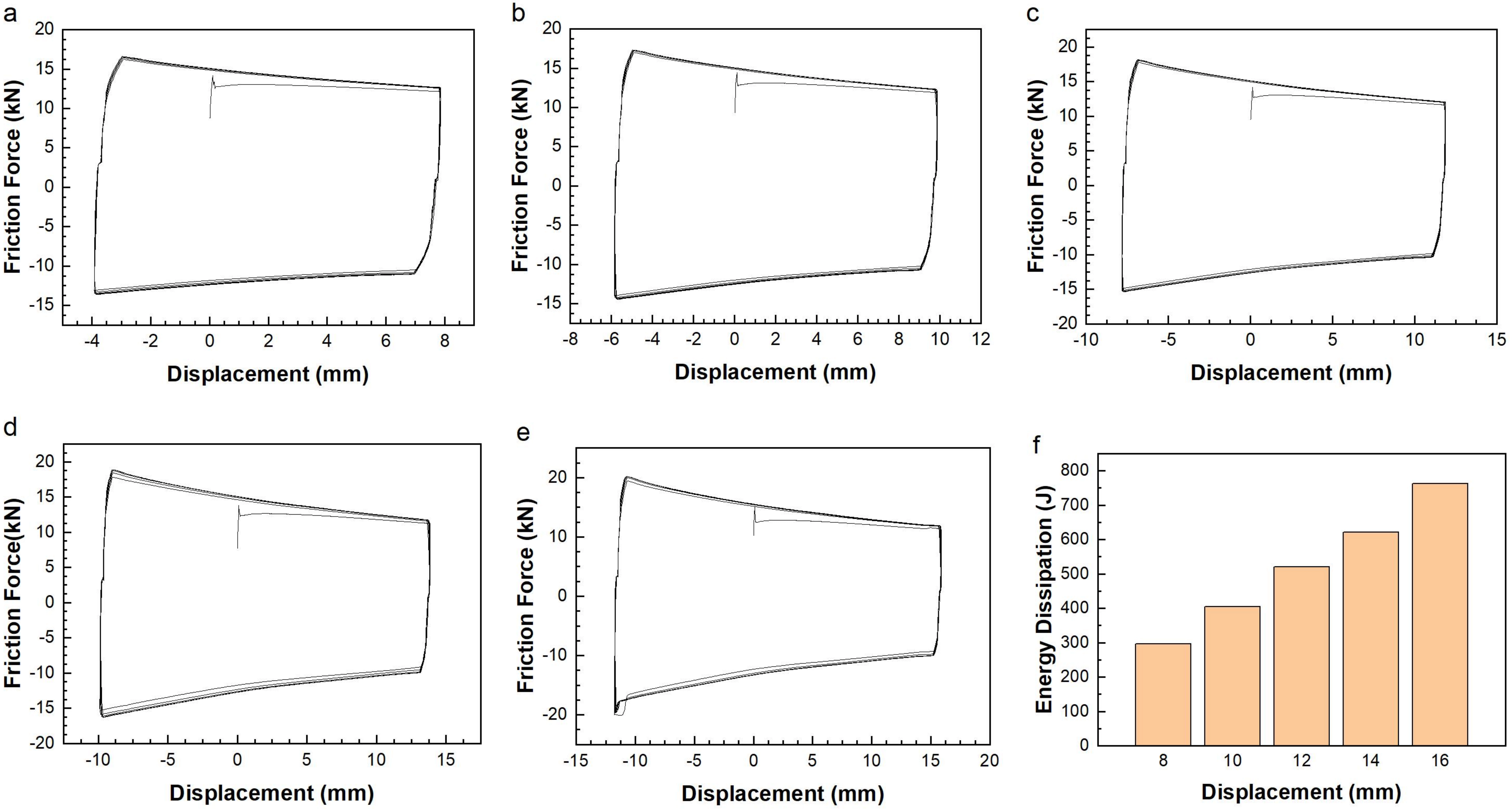
Figure 5. Friction force-displacement hysteresis curves under different displacement amplitudes. (a) 8 mm; (b) 10 mm; (c) 12 mm; (d) 14 mm; (e) 16 mm; (f) Comparison of energy dissipation under different displacement amplitudes.
For the third group of test conditions in Table 1, under identical displacement and velocity circumstances, the hysteresis curves of the self-sensing friction damper with varying bolt torques, indicating varying friction force, are presented in Figure 6a,b,c,d. When the torque is relatively small, the difference in friction force among different loading cycles is minimal, and the hysteresis curve remains stable. When the torque is relatively large, the friction force slightly diminishes with the increase in the number of loading cycles, and the hysteresis curve fluctuates. By integrating the stable hysteresis curves under the aforesaid conditions, the single-cycle energy dissipation of the self-sensing damper under different friction forces is obtained, as shown in Figure 6e. As the friction increases, the energy dissipation of the friction damper rises. However, when the friction force exceeds 30.8 kN, the increase in energy dissipation is small. Upon disassembling the damper and observing the friction plate, it can be found that when the friction force exceeds 30.8 kN, there was some PVC attached to the steel plate.
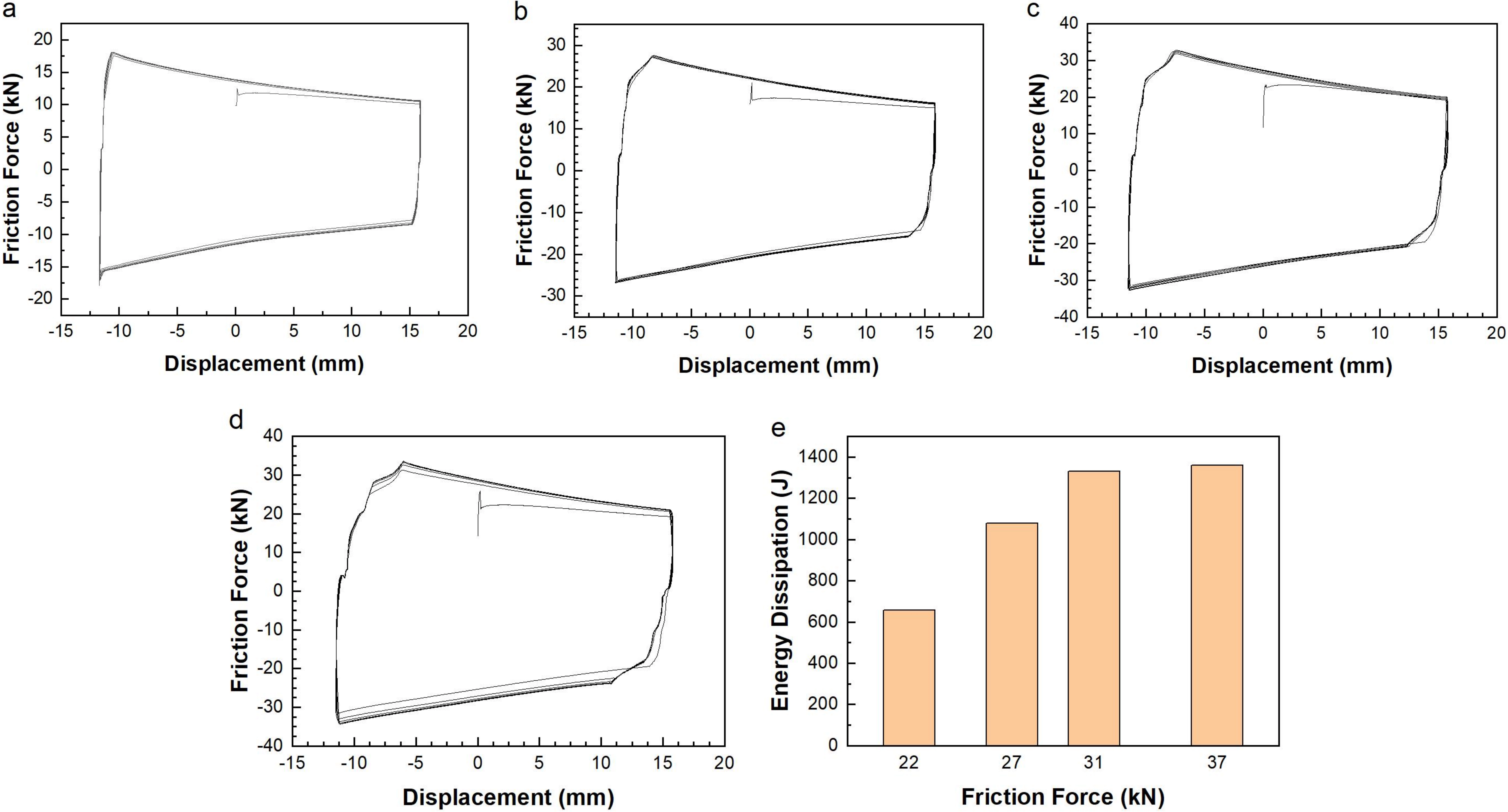
Figure 6. Friction force-displacement hysteresis curves under different friction forces. (a) 22 kN; (b) 27.4 kN; (c) 30.8 kN; (d) 37.1 kN; (e) Comparison of energy dissipation under different friction forces.
It can be inferred that as the friction force increases to a certain threshold, a portion of the PVC plate adheres to the surface of the stainless steel plate, resulting in a decrease in the friction coefficient. Therefore, when the bolt preload increases, the increase in friction force is small. In practical engineering applications, the friction force is generally fixed at a preset value. Through the research on this part of the working conditions, the output of the self-sensing friction damper can be reasonably designed to better meet engineering requirements.
5. Sensing Properties of Self-Sensing Friction Damper
5.1 Relationship between voltage, current, and velocity
For the first group of test conditions in Table 1, under the same friction force, displacement, and different velocity conditions, cyclic loading is carried out six times. The time history curves of voltage and displacement at different velocities are measured and presented in Figure 7a,b,c,d,e. It can be observed that displacement and voltage change in the same phase, which complies with the V-Q-x relationship of general TENGs. Under the working conditions of 2 mm/s and 4 mm/s, the voltage signal exhibits a slight jitter. This is because the movement velocity is relatively slow, which amplifies the slip effect of the component. When the velocity is relatively large, this jitter phenomenon vanishes. Taking the average of the voltage amplitude changes under each velocity condition and analyzing the relationship between velocity and voltage, as shown in Figure 7f. As seen from the figure, as the sliding velocity increases, the voltage increases synchronously and shows good linearity. However, this relationship is different from the law that the velocity and voltage of general TENGs are independent. The possible reason is that the friction force of the self-sensing friction damper is significantly increased compared to general TENGs, thus affecting the relationship between velocity and voltage.
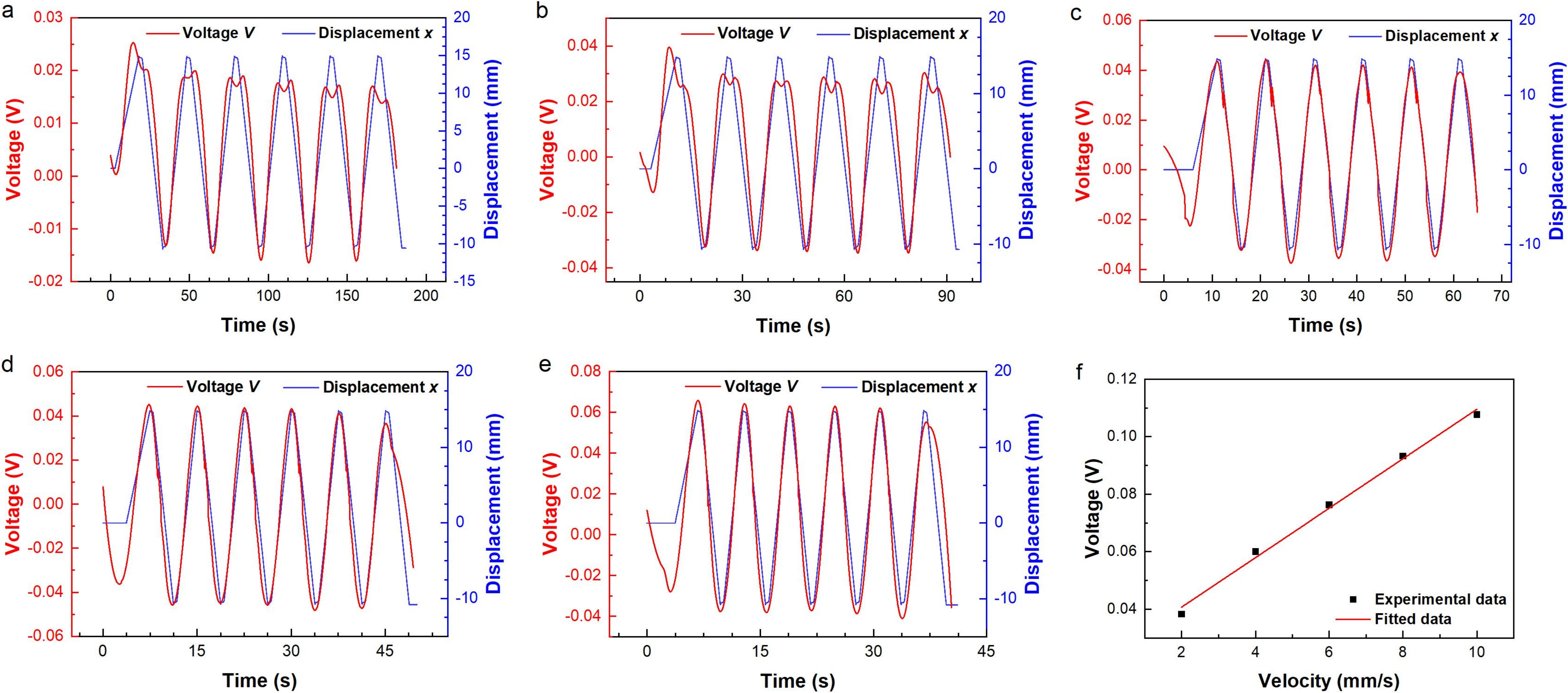
Figure 7. Time-history curves of voltage and displacement under different velocities. (a) 2 mm/s; (b) 4 mm/s; (c) 6 mm/s; (d) 8 mm/s; (e) 10 mm/s; (f) Voltage-velocity relationship.
The time history curves of displacement and current at different velocities are shown in Figure 8a,b,c,d,e. As can be observed from this figure, the current and displacement have a half-phase difference, which is in accordance with the general law of TENGs. At low sliding velocity (2 mm/s, 4 mm/s, and 6 mm/s), the current curve fluctuates when the forward displacement reaches its maximum. The reason for this is the same as the fluctuation in the voltage-displacement relationship at low velocity. Namely, when the sliding velocity is slow, the bolt slip phenomenon of the self-sensing friction damper due to manufacturing errors is more prominent. However, when the sliding velocity is faster, this influence is relatively reduced. The average value of the current amplitude changes under each velocity condition is obtained to analyze the relationship between velocity and current, as shown in Figure 8f.
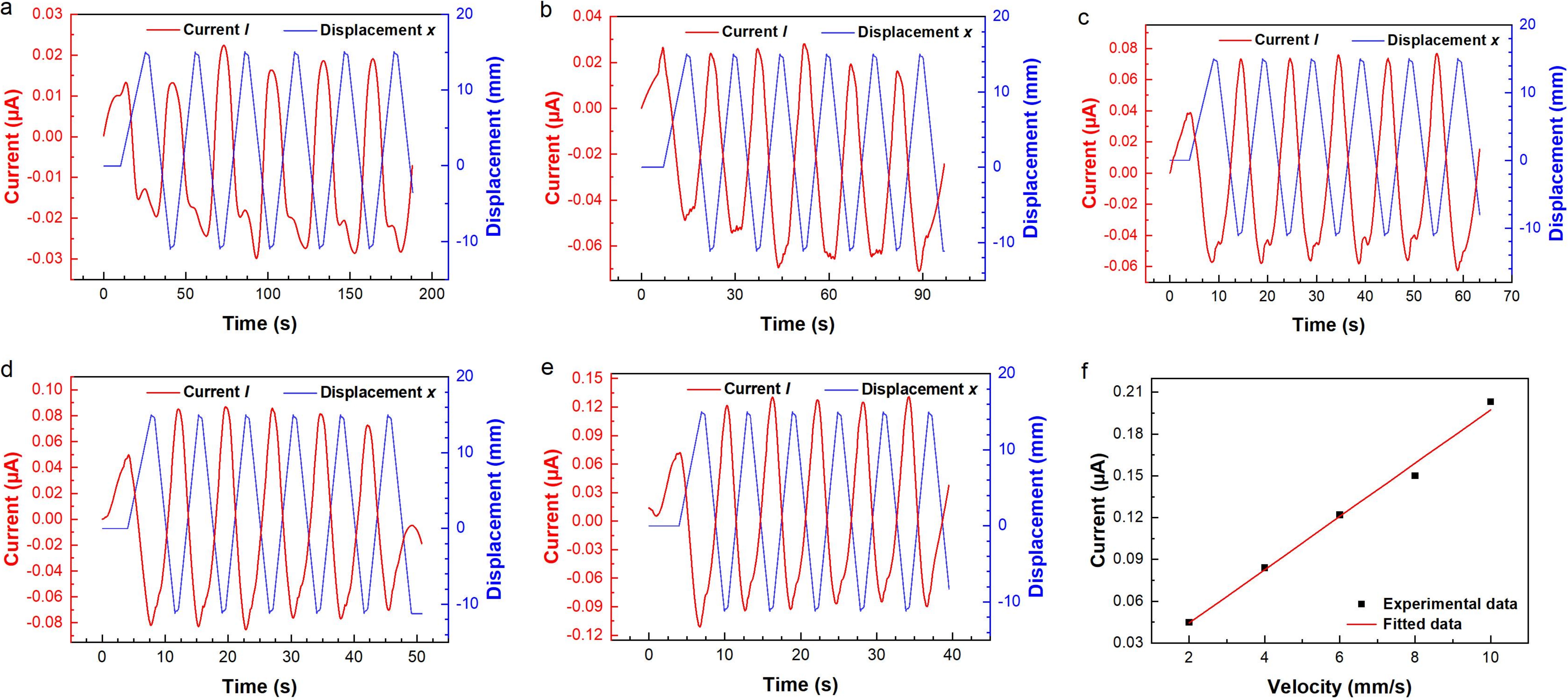
Figure 8. Time-history curves of current and displacement under different velocities. (a) 2 mm/s; (b) 4 mm/s; (c) 6 mm/s; (d) 8 mm/s; (e) 10 mm/s; (f) Current-velocity relationship.
As seen from the figure, as the sliding velocity increases, the current increases synchronously and exhibits good linearity, conforming to the general rule that the current of TENGs is proportional to the velocity.
5.2 Relationship between voltage, current, and displacement
For the second group of test conditions in Table 1, cyclic loading is carried out six times under the same friction force, velocity, and different displacement conditions. The time history curves of voltage and displacement under different stroke conditions are measured and shown in Figure 9a,b,c,d,e. It can be observed that displacement and voltage change in the same phase, which conforms to the V-Q-x relationship of general TENGs. The voltage signal exhibits slight jitter, which is due to the slower movement velocity and the amplification of the slip effect of the component. By calculating the average value of voltage amplitude changes under different stroke conditions and analyzing the relationship between displacement and voltage, as shown in Figure 9f. As the stroke increases, the voltage signal generated by the damper correspondingly increases, and the linearity is good. This is because the greater the separation distance between the PVC plate and the steel plate, the greater the potential difference between the two plates, which is in line with the V-Q-x relationship of general TENGs. In practical engineering applications, the displacement state of the damper can be obtained by monitoring the voltage signal.
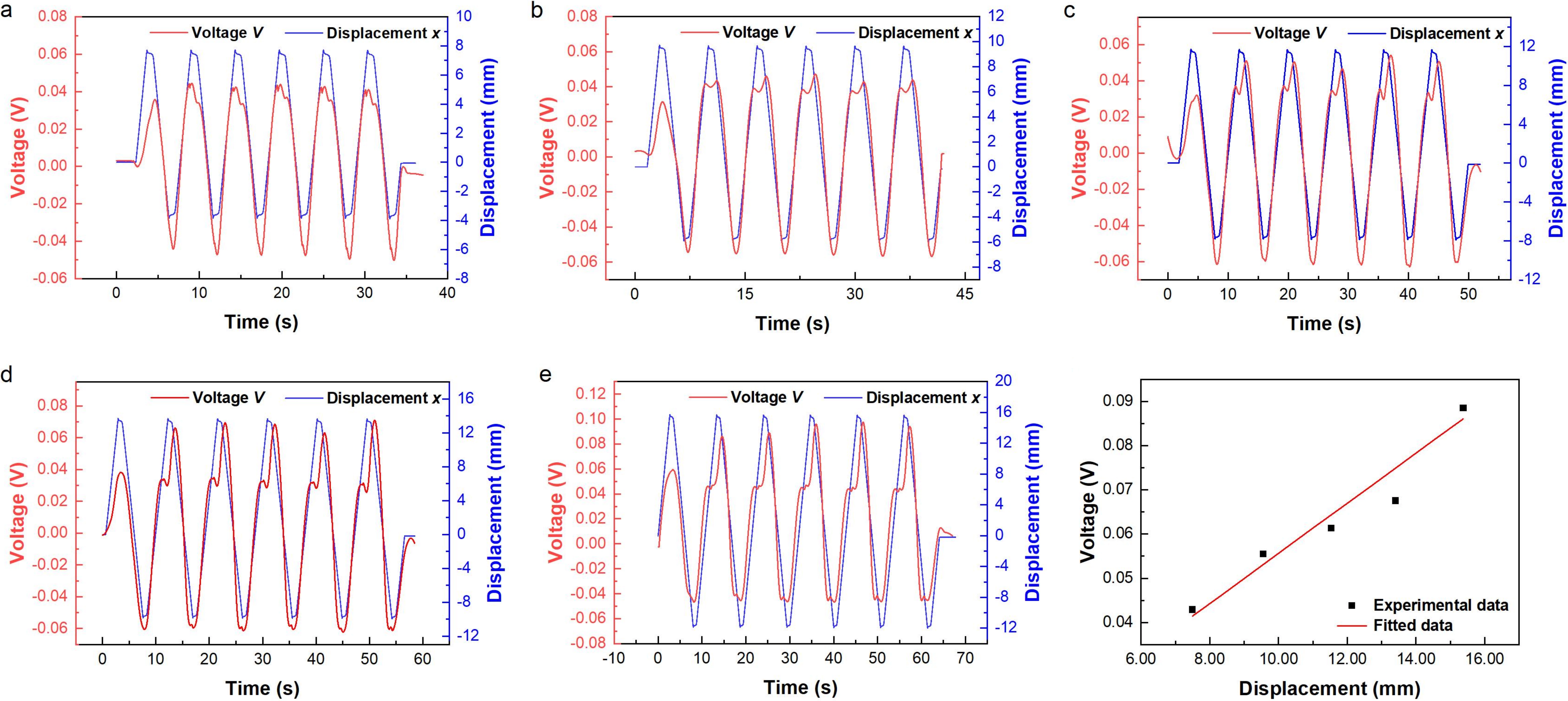
Figure 9. Time-history curves of voltage and displacement under different displacement amplitudes. (a) 2 mm/s; (b) 4 mm/s; (c) 6 mm/s; (d) 8 mm/s; (e) 10 mm/s; (f) Voltage-displacement relationship.
The current-displacement curves measured under various stroke conditions are presented in Figure 10a,b,c,d,e. As can be observed from the figure, the current lags behind the displacement by half a phase, which is in accordance with the law of general TENGs. During different loading cycles, the amplitude of current change fluctuates significantly. The possible reason is that the friction of the self-sensing friction damper designed in this paper is relatively large, and the flow of electrons in the circuit is affected by the wear on the friction surface. By calculating the average value of the current amplitude change under each displacement condition and analyzing the relationship between the displacement of the damper and the current, as shown in Figure 10f. As seen from this figure, there is no obvious change in the current as the displacement increases. The slight fluctuation may be related to the change in the friction surface. Therefore, the current is not suitable for monitoring the displacement of the damper.
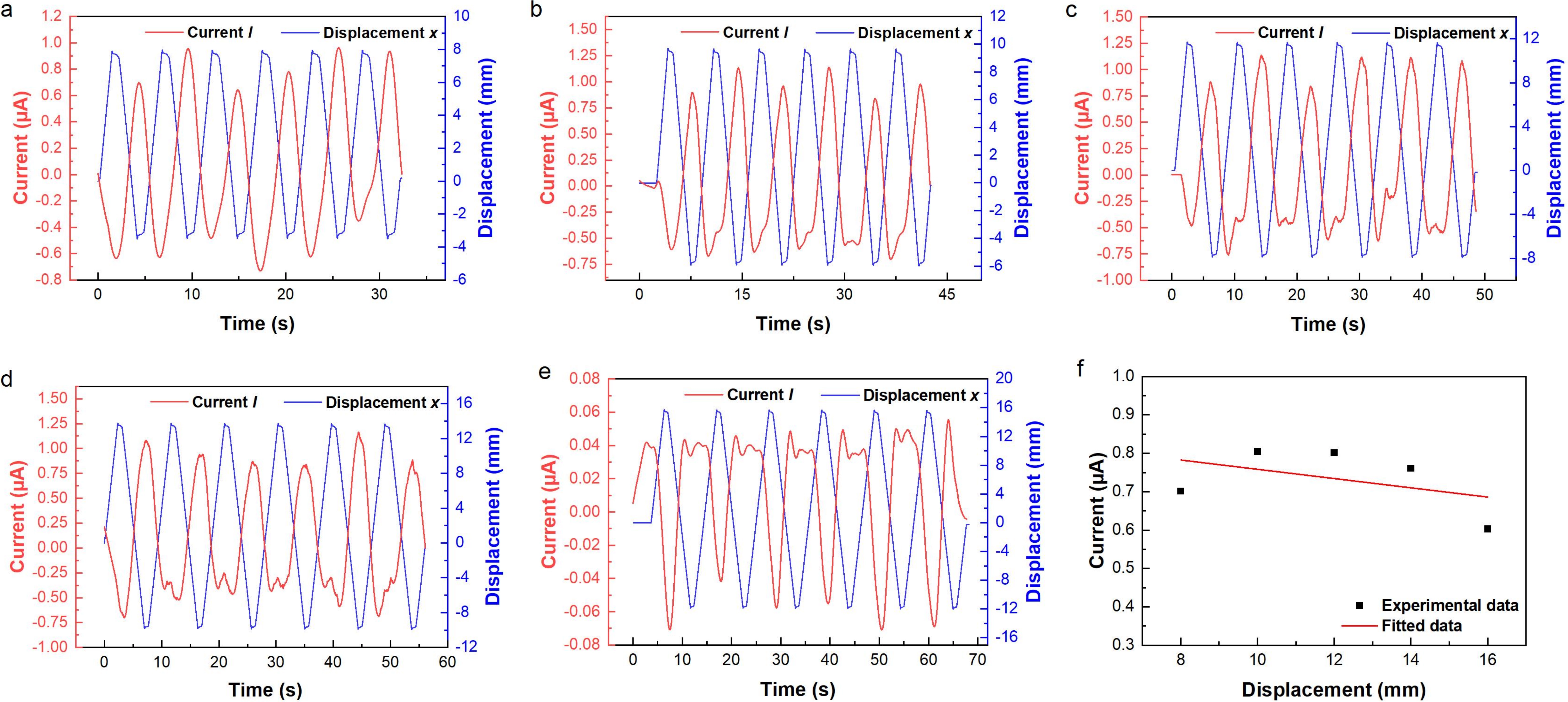
Figure 10. Time-history curves of current and displacement under different displacement amplitudes. (a) 2 mm/s; (b) 4 mm/s; (c) 6 mm/s; (d) 8 mm/s; (e) 10 mm/s; (f) Current-displacement relationship.
5.3 Sensing property analysis
Sensitivity is a crucial indicator in evaluating sensor performance. It represents the ratio of the sensor’s output increment to the input increment. When the variation range of the input physical signal remains the same, a larger variation range of the output electrical signal indicates higher sensitivity, enabling easier detection of minute changes in the measured physical quantity. Linearity is primarily an indicator that reflects the accuracy characteristics of the sensor and characterizes the extent to which the sensor performance accomplishes the intended measurement.
As evident from the previous analysis, voltage can be utilized to monitor the displacement of the damper itself, while current can be employed to monitor the sliding velocity of the damper. The sensing performance of the voltage-displacement and current-velocity relationships is evaluated from two aspects, sensitivity and linearity. The designed self-sensing friction damper has a sensitivity of 0.00526 V/mm. The smaller the linearity value of the sensor, the better its measurement accuracy within the measured range. The linearity of the self-sensing damper designed in this paper is ±1.762%, and the measurement accuracy meets engineering requirements. At the same time, the R2 value of the voltage-displacement linear fitting reaches 0.94. This slightly lower linearity (compared to the current-velocity fitting) is primarily attributed to the direct sensitivity of the voltage signal to mechanical errors in displacement measurement, such as minor vibrations or clearances in the loading system. These disturbances introduce local fluctuations into the displacement signal, which are directly reflected in the voltage output.
For the relationship between current and velocity, the designed self-sensing friction damper has an induction sensitivity of 0.01914 μA/(mm/s) for its own sliding velocity. Its linearity value is small, and the measurement accuracy can meet actual engineering requirements. In the linear fitting of current-velocity, the fitted R2 value reaches more than 0.99, as the current signal, being proportional to the rate of change of displacement, is less affected by low-frequency mechanical perturbations due to the inherent smoothing effect of differentiation. This indicates that the linear fitting can well reflect the relationship between current and velocity.
6. Influence of Friction Force on The Sensing Performance of Self-Sensing Friction Dampers
The triboelectrification process is influenced by multiple factors, including humidity[34] and temperature[35]. The friction force of the developed self-sensing friction damper during operation is significantly larger than that of conventional TENG sensors. This results in the power generation law under a strong friction environment exhibiting a pattern different from that of general TENGs. For instance, in the aforementioned experimental results, the voltage is linearly dependent on the velocity, whereas the voltage of a general TENG is independent of the velocity. This work primarily considers the influence of friction temperature and interface wear amount on triboelectric power generation and sensing performance.
Maintain a sliding velocity of 6 mm/s and a displacement of 16 mm. Control the torque of the bolt using a torque wrench to achieve control over the friction force. Set up seven working conditions to study the influence of friction force on the voltage, current, and charge of the self-sensing friction damper.
The time-history curves of voltage and displacement under different friction conditions are presented in Figure 11a,b,c,d,e,f,g. As can be seen from the figure, the time-history of voltage is synchronized with that of displacement under each working condition, but exhibits fluctuations to varying degrees. Particularly under the friction force of 34.2 kN, the voltage signal fluctuates more significantly. The possible reasons are, on one hand, the influence of the thermal effect in the friction process on triboelectrification, and on the other hand, the influence of interface wear.
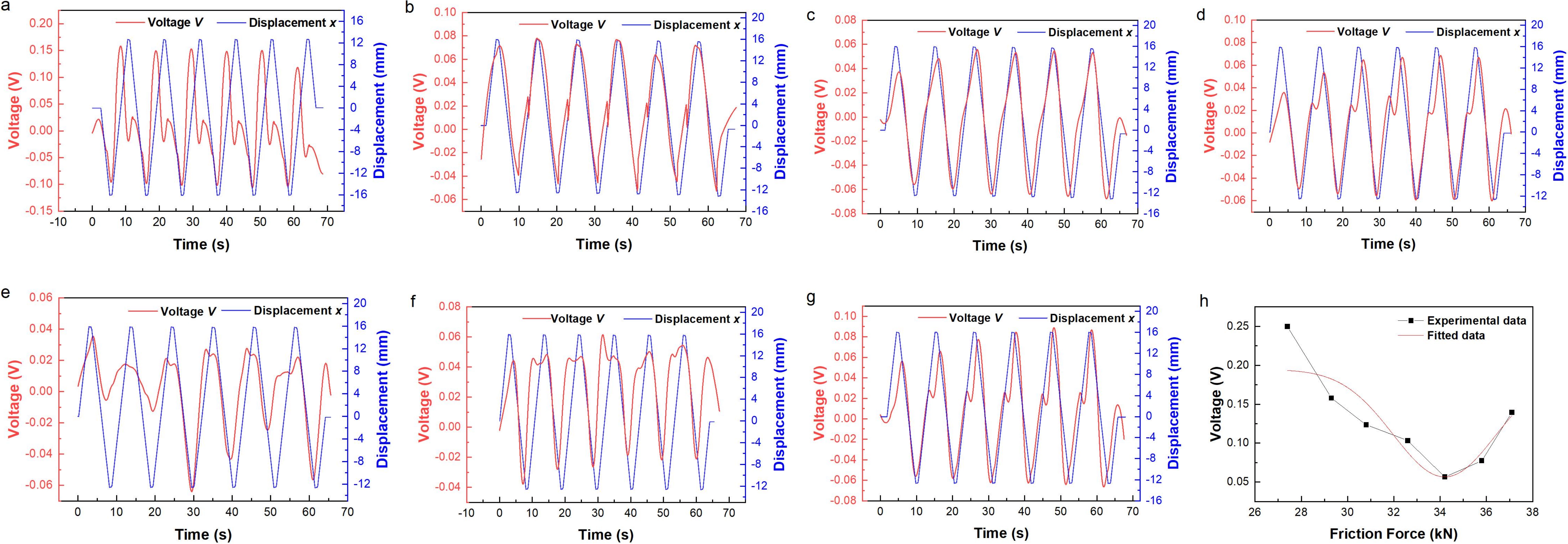
Figure 11. Time-history curves of voltage and displacement under different friction forces. (a) 27.4 kN; (b) 29.3 kN; (c) 30.8 kN; (d) 32.6 kN; (e) 34.2 kN; (f) 35.8 kN; (g) 37.1 kN; (h) Relationship between voltage and friction force.
The mean value of the amplitudes of voltage variation under different friction force working conditions is calculated to obtain the curve of the relationship between voltage and friction force, as illustrated in Figure 11h. It can be observed that a nonlinear relationship exists between voltage and friction force. Initially, the amplitude of voltage variation decreases as the friction force increases. When the friction force exceeds 34.2 kN, the amplitude of voltage variation increases as the friction force increases. Evidently, the influence of friction force on the triboelectric effect is relatively complex and should be fully taken into account when designing self-sensing friction dampers.
Under diverse friction force conditions, the time-history curves of current and displacement are presented in Figure 12a,b,c,d,e,f,g. It can be observed from the figure that the current signal varies in accordance with the reciprocal alteration of displacement, and there is a half-phase difference from the displacement change cycle. When different friction forces are applied, the current signal exhibits fluctuations to varying degrees. Notably, under the friction force of 34.2 kN, the current signal fluctuates more conspicuously. The possible causes are, on one hand, the impact of the thermal effect during the frictional process on triboelectricity, and on the other hand, the influence of interface wear.
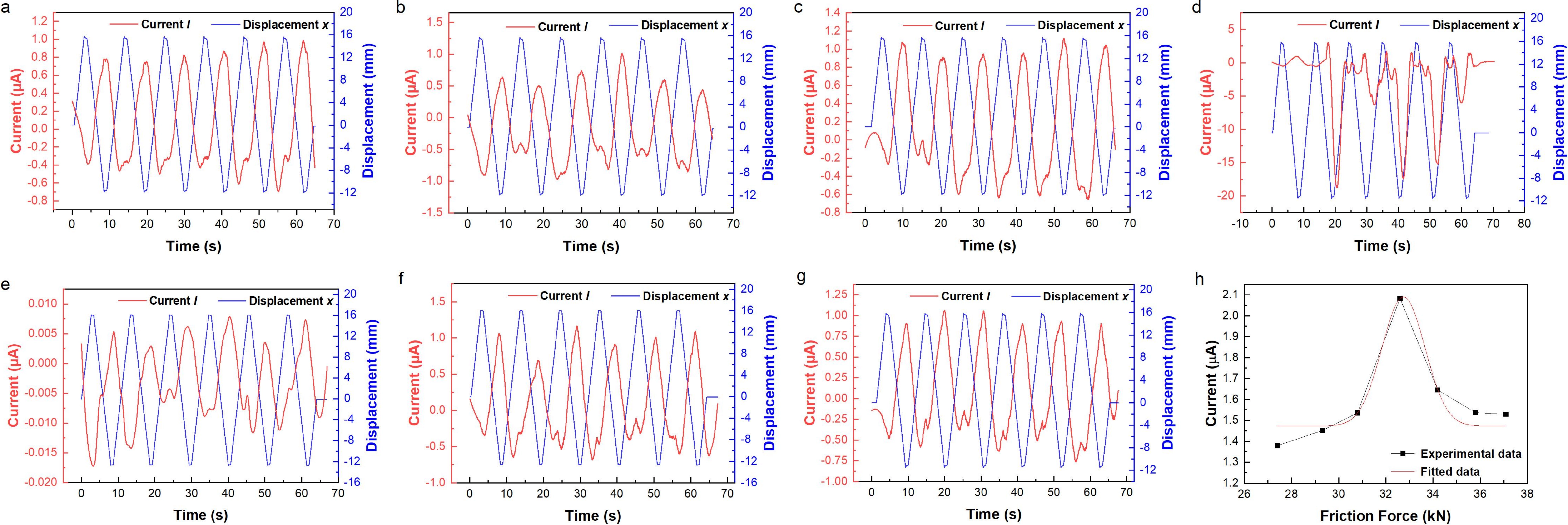
Figure 12. Time-history curves of current and displacement under different friction forces. (a) 27.4 kN; (b) 29.3 kN; (c) 30.8 kN; (d) 32.6 kN; (e) 34.2 kN; (f) 35.8 kN; (g) 37.1 kN; (h) Relationship between current and friction force.
The calculation of the mean value of the amplitudes of current variation under different friction force working conditions, thereby obtaining the relationship curve between current and friction force, is illustrated in Figure 12h. It can be observed that a nonlinear relationship exists between current and friction force. Initially, the amplitude of current variation increases as the friction force rises. When the friction force exceeds 32.6 kN, the amplitude of current variation decreases as the friction force increases. This phenomenon demonstrates that the influence of friction force on the triboelectric effect is relatively complex.
7. Mechanism Analysis
In this study, the relationship between voltage and velocity obtained differs from that of a conventional TENG. A favorable linear relationship between voltage and velocity exists, which implies that under these frictional conditions, other factors predominantly influence the electrification rules of the self-sensing frictional damper.
The research[36] has demonstrated that the temperature difference between two frictional contact materials can affect their electrification effect. A solid with a higher temperature tends to carry positive frictional charge, whereas a solid with a lower temperature tends to carry negative charge. Consequently, it is indicated that the charge transfer caused by the temperature difference can be ascribed to the thermionic emission effect, that is, electrons are thermally excited and transferred from the hotter surface to the colder one, and a temperature difference due to friction between two surfaces with different curvatures or surface roughness exists. In engineering, when two surfaces are in contact, local inhomogeneities will lead to non-uniform contact, thereby causing changes in the local temperature of the entire surface, and thus local electron rearrangement occurs at the frictional interface.
According to the previous theory, when the separation displacement remains unchanged, the variation in sliding velocity intensifies the electron rearrangement. In this study, an infrared temperature tester was employed to monitor the temperature of the self-sensing frictional damper under different velocity conditions to explore the temperature change at the frictional interface, as shown in Figure 13a,b,c,d,e. It can be observed from the figure that as the sliding velocity increases, the temperature at the interface friction of the self-sensing frictional damper also rises. To better determine the relationship between the two, the collected interface temperature and sliding velocity were plotted as the temperature-sliding velocity relationship depicted in Figure 13f. It can be seen that as the sliding velocity increases, the interface temperature also increases, and their R2 is greater than 0.99, indicating good linearity. Hence, it is considered that the temperature is positively correlated with the sliding velocity.
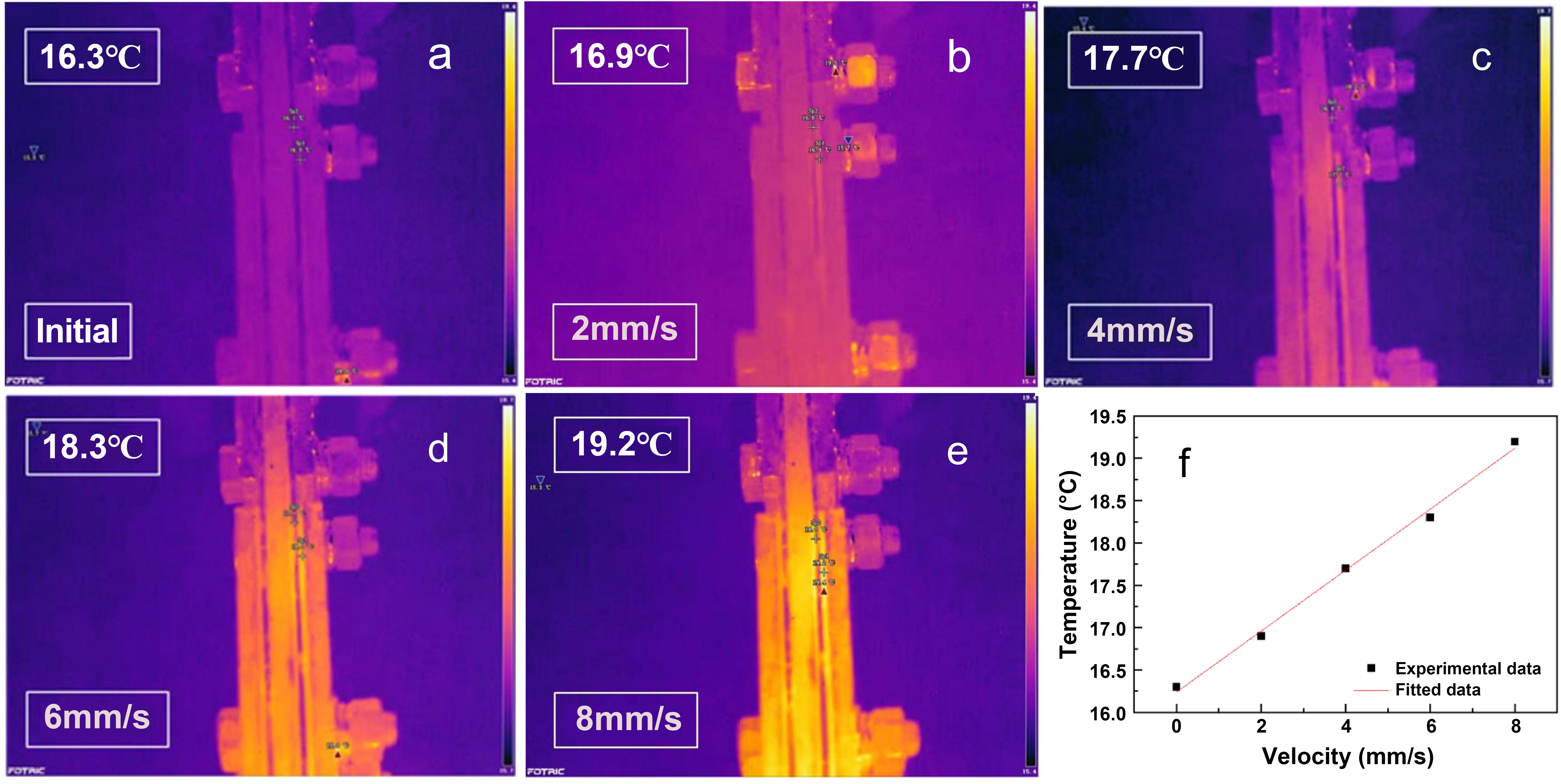
Figure 13. Temperature of self-sensing friction damper under different velocities. (a) 0 mm/s; (b) 2 mm/s; (c) 4 mm/s; (d) 6 mm/s; (e) 8 mm/s; (f) Interface temperature-velocity relationship.
Combined with the above-mentioned electron rearrangement effect in triboelectrification, the rules of voltage-velocity, which are different from those of a conventional TENG, are explained. Under strong friction force, friction generates a relatively high temperature, and the uneven protrusions on the surface of the friction plate cause a local increase in the temperature of the friction plate. The increase in temperature leads to a local redistribution of electrons, which subsequently causes a change in the potential of the friction plate. As the sliding velocity increases, this phenomenon becomes more pronounced. Therefore, under the same sliding displacement, the potential at the PVC-steel plate frictional interface decreases more. To ensure charge conservation, more charges are introduced from the ground. Finally, as the sliding velocity increases, the interface temperature rises, the potential drops more significantly, resulting in an increase in voltage. In this process, the frictional temperature becomes the dominant factor in these frictional conditions, causing its triboelectrification rules to differ from those of a general self-sensing frictional damper.
It can be seen from the previous experimental results that in the relationships between voltage, current, charge, and friction force, an inflection point appears near 34.2 kN. During these testing processes, parameters such as velocity and separation displacement did not change, and the influence of temperature and separated charges can be excluded. A reasonable explanation is that the accumulation of wear has led to the emergence of this special phenomenon.
To verify this hypothesis, this work conducts a microscopic analysis on the surface of the frictional steel plate post-friction. Firstly, with the sliding velocity (6 mm/s) and the maximum sliding displacement (16 mm) remaining unchanged, four specimens are designed. Subsequently, bolt torques of 60 N·m, 70 N·m, 80 N·m, and 90 N·m are respectively applied to each specimen, which correspondingly generate friction force of 27.4 kN, 30.8 kN, 34.2 kN, and 37.1 kN, respectively. Under each working condition, cyclic loading is carried out for 12 cycles, and then sampling analysis is performed on the surface of the frictional steel plate. For the purpose of comparing the wear amounts of each plate, samples are taken from the identical positions on both the upper and lower parts of each frictional plate (Figure 14). Thereafter, the samples are observed using a SEM.
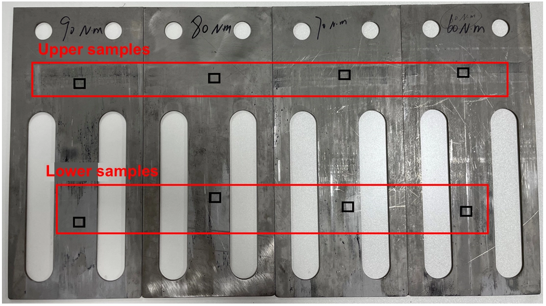
Figure 15 presents the electron microscope results of the upper sample group. The positions marked with red circles in the figures represent the friction-wear areas of the stainless-steel plate. Based on the quantity of these wear areas, a qualitative assessment of the wear amount of the friction plate under this friction force is made. The highly reflective white areas are the adhered PVC debris. As can be observed from the figures, when the friction force rises from 27.4 kN to 30.8 kN, the amount of wear caused by friction increases, and the amount of PVC residue also rises. As the friction force further increases to 34.2 kN, the frictional wear amount reaches its peak; when the friction force continues to increase to 37.1 kN, the wear amount does not experience a significant increase. Consequently, an inflection point of the wear amount is observed in the upper sample group when the friction force is 34.2 kN. Before this inflection point, the wear amount increases with the growth of the friction force, and after this point, the wear amount decreases substantially.
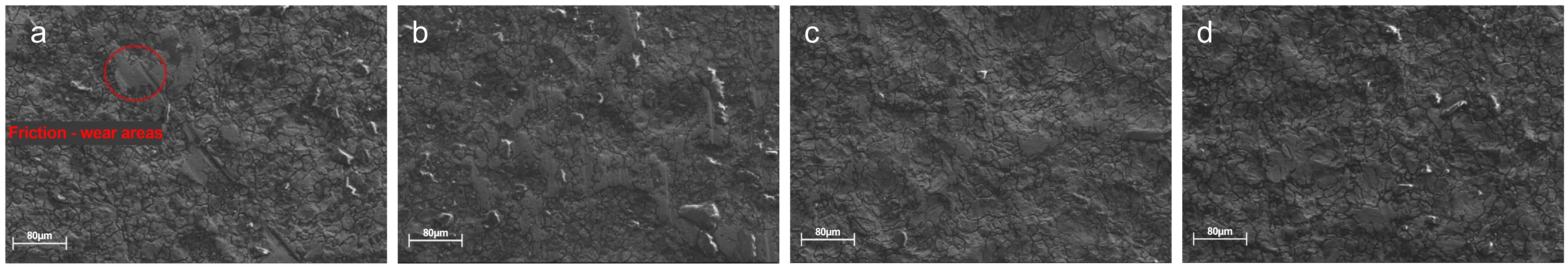
Figure 15. SEM image of the upper sample of the friction plate. (a) 27.4 kN; (b) 30.8 kN; (c) 34.2 kN; (d) 37.1 kN. SEM: scanning electron microscopy.
The lower sample group is also examined using a scanning electron microscope, and the results are shown in Figure 16. As can be seen from the figures, the variation in the wear amount of the lower sample group is in line with that of the upper sample group. When the friction force is 34.2 kN, the wear amount reaches its maximum, and then the wear amount decreases. This phenomenon is attributed to the peeling and formation of the oxide layer on the surface of the stainless-steel plate. Before the inflection point, the original oxide layer of the steel plate is frictionally peeled off, leading to an increase in the wear amount of the friction surface. As the friction force continues to increase beyond the inflection point, the friction temperature rises, causing the materials in the surface layer to soften and recrystallize, and a new oxide film is formed, resulting in a corresponding decrease in the wear amount. As shown in Figure 16c,d, the turtle-shell-like cracks in the unworn parts are larger than those in Figure 16a,b, indicating the change in the oxide film. Through the analysis of the SEM images of the upper and lower sample groups, it is concluded that when the friction force is 34.2 kN, the wear amount reaches its maximum, which is basically in agreement with the peak inflection points of the relationships between friction force and current, voltage, and charge amount.
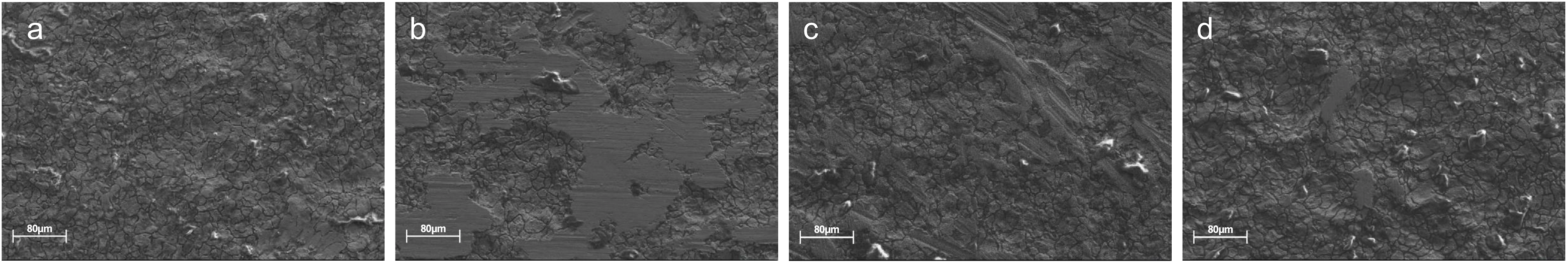
Figure 16. SEM image of the lower sample of the friction plate. (a) 27.4 kN; (b) 30.8 kN; (c) 34.2 kN; (d) 37.1 kN. SEM: scanning electron microscopy.
In summary, in a high-frictional-force environment, the dominant factor influencing the power-generation performance of the TENG by changing the friction force is the change in the amount of frictional wear. When designing similar dampers, it is necessary to be aware of the magnitude of the designed sliding friction force and strive to avoid the above-mentioned friction forces that affect the self-sensing performance.
The existing theory of TENGs is applicable to working conditions with relatively low friction forces, without taking into account the influence of strong friction forces on their sensing performance. Based on the data collected from experiments, this paper proposes an empirical relationship formula of Q-V-f. As depicted in Figure 11h and Figure 12h, the Gaussian formula is employed to fit the relationships between voltage-friction force and current-friction force, and the fitting results are in good accordance with the experimental values.
In a strong-frictional-force environment, the relationship between the voltage V between the two friction plates of the self-sensing friction damper and the friction force f is given as follows:
where ɑ represents the voltage change coefficient, V0 is the initial surface voltage, f denotes the magnitude of the friction force, ω is the voltage-curve adjustment coefficient, and fc is the critical friction force.
By substituting the voltage V obtained from equation (4) into the V-Q-x relationship of the TENG in equation (1), the Q-V-f empirical formula in a strong-frictional-force environment can be derived:
where VOC(x) is the open-circuit voltage.
The above formula comprehensively takes into account the friction force in a strong-frictional-force environment, including the critical friction force fc that affects the sensing performance, the initial voltage V0 on the surface of the friction plates, and the magnitude of the capacitance C(x) affected by the sliding distance. This relationship formula serves as a supplement and improvement to the triboelectric generation law and has theoretical guiding significance for the design of self-sensing friction dampers.
8. Conclusions
A self-sensing friction damper with energy dissipation and sensing characteristics was developed based on the single-electrode horizontal sliding mode of TENGs, using PVC and steel as friction pairs in a multilayered structure. Experimental results confirm stable energy dissipation performance: energy dissipation is independent of sliding velocity but increases linearly with displacement (300-770 J over 8-16 mm). While friction force enhances dissipation, the rate slows beyond a threshold due to reduced friction coefficient from PVC adhesion to steel. The damper exhibits robust sensing capabilities: voltage correlates linearly with displacement (sensitivity: 0.00526 V/mm, linearity: ±1.762%, R2 = 0.94), and current correlates linearly with velocity (sensitivity: 0.01914 μA/(mm/s), linearity: ±4.449%, R2 > 0.99), meeting engineering requirements. Friction force exerts complex nonlinear effects on triboelectrification, with maximum wear observed at 34.2 kN, consistent with inflection points in voltage-friction and current-friction relationships. This highlights frictional wear as the dominant factor in high-friction environments. An empirical Q-V-f formula is proposed to describe triboelectric behavior under high friction, supplementing triboelectric theory and guiding damper design by optimizing friction force to balance dissipation and sensing stability.
Supplementary materials
The supplementary material for this article is available at: Supplementary materials.
Acknowledgements
The authors confirm that Doubao was used to assist in the preparation of this paper. The specific usage scenario includes: language polishing, grammar checking, and adjusting expressions to better conform to English writing conventions. The authors have reviewed and take full responsibility for all content of the final manuscript.
Authors contribution
Ma N: Writing-original draft, funding acquisition, supervision, conceptualization.
Ming H: Investigation, formal analysis, validation.
Zhang S: Investigation, data curation, validation, methodology.
Zhou L, Zhang C: Visualization, conceptualization.
Dong X: Writing-review & editing, supervision, resources, funding acquisition, project administration.
Conflicts of interest
Ning Ma is a Youth Editorial Board Member of Smart Materials and Devices. The other authors declare no conflicts of interest.
Ethical approval
Not applicable.
Consent to participate
Not applicable.
Consent for publication
Not applicable.
Availability of data and materials
Data supporting the findings of this study are available from the corresponding author upon reasonable request.
Funding
This research was funded by Dalian Science and Technology Innovation Program (Grant No. 2024JJ12CG032), National Natural Science Foundation of China (Grant No. 52178459), and Beijing Natural Science Foundation (Grant No. L247020).
Copyright
© The Author(s) 2026.
References
-
1. Yao JTP. Concept of structural control. J Struct Div. 1972;98(7):1567-1574.[DOI]
-
2. Arvind R, Santhi MH. A state of art review on hybrid passive energy dissipating devices. J Vib Eng Technol. 2022;10(5):1931-1954.[DOI]
-
3. Yang F, Sedaghati R, Esmailzadeh E. Vibration suppression of structures using tuned mass damper technology: A state-of-the-art review. J Vib Control. 2022;28:812-836.[DOI]
-
4. Chowdhury S, Banerjee A, Adhikari S. The optimal design of negative stiffness inerter passive dampers for structures. Int J Mech Sci. 2023;258:108551.[DOI]
-
5. Shu Z, You R, Xie Y. Viscoelastic dampers for vibration control of building structures: A state-of-art review. J Earthq Eng. 2024;28(12):3558-3585.[DOI]
-
6. Zhang H, Li A, Su Y, Xu G, Sha B. Viscoelastic dampers for civil engineering structures: A systematic review of constructions, materials, and applications. J Build Eng. 2024;96:110597.[DOI]
-
7. Almajhali KYM, Alhaddad W. A systematic review of hybrid passive energy dissipating devices. Proc Inst Civ Eng Struct Build. 2025;178(3):248-263.[DOI]
-
8. Soong TT, Dargush GF. Passive energy dissipation systems in structural engineering. New York: John Wiley & Sons; 1997. Available from: https://www.semanticscholar.org/paper/f5fbe216ca41c84d206bd6a782dc2f79a2ed18f0
-
9. Abdelrahman M, Fan C, Yi M, Zhang Z, Ali A, Xia X, et al. Variable damping energy regenerative damper for self-powered sensors and self-sensing devices in smart electric buses. Smart Mater Struct. 2024;33(10):105009.[DOI]
-
10. Qin A, Zhang B, Ning D, Tan B, Du H. A self-sensing approach for estimating suspension displacement and velocity in semi-active electromagnetic dampers. Mech Syst Signal Process. 2024;208:111049.[DOI]
-
11. Zhang M, Yang W. Research on the sensing properties and vibration reduction performance of self-sensing self-tuning magnetic fluid damper. Meas Sci Technol. 2025;36(1):015121.[DOI]
-
12. Xu Q, Sun R, Liu Y, Li Q, Cheng L. Self-sensing electromagnetic shunt damper for adaptive vibration control. Smart Mater Struct. 2025;34(10):105021.[DOI]
-
13. Zhu TY, Yuan Y, Zi DM, Cui WS. A viscous damper with controllable damping force and its intelligent monitoring and control system. CN Patent 203202108U. 2013 Sep 18. Chinese. Available from: https://patentimages.storage.googleapis.com/CN203202108U.pdf
-
14. Lam KH, Chen ZH, Ni YQ, Chan HLW. A magnetorheological damper capable of force and displacement sensing. Sens Actuat A Phys. 2010;158(1):51-59.[DOI]
-
15. Jaisee S, Yue F, Ooi YH. A state-of-the-art review on passive friction dampers and their applications. Eng Struct. 2021;235:112022.[DOI]
-
16. Bhaskararao AV, Jangid RS. Seismic analysis of structures connected with friction dampers. Eng Struct. 2006;28(5):690-703.[DOI]
-
17. Asfaw AM, Cao L, Ozbulut OE, Ricles J. Development of a shape memory alloy-based friction damper and its experimental characterization considering rate and temperature effects. Eng Struct. 2022;273:115101.[DOI]
-
18. Ferrotto MF, Cavaleri L. Variable Friction Dampers (VFD) for a modulated mitigation of the seismic response of framed structures: Characteristics and design criteria. Probab Eng Mech. 2022;70:103375.[DOI]
-
19. Artar M, Carbas S. Optimum sizing design of steel frame structures through maximum energy dissipation of friction dampers under seismic excitations. Structures. 2022;44:1928-1944.[DOI]
-
20. Kim YC, Lee HW, Hu JW. Experimental performance evaluation of elastic friction damper. Case Stud Constr Mater. 2023;18:e01823.[DOI]
-
21. Gao J, Wang CL, Meng S, Zeng B. Performance evaluation of friction dampers considering different metal pairs and loading rates. J Constr Steel Res. 2023;204:107859.[DOI]
-
22. Wang ZL. Triboelectric nanogenerators as new energy technology for self-powered systems and as active mechanical and chemical sensors. ACS Nano. 2013;7(11):9533-9557.[DOI]
-
23. Wang ZL, Lin L, Chen J, Niu S, Zi Y. Triboelectric nanogenerator: Single-electrode mode. In: Triboelectric nanogenerators. Cham: Springer; 2016. p. 91-107.[DOI]
-
24. Wang ZL, Lin L, Chen J, Niu S, Zi Y. Triboelectric nanogenerator: Freestanding triboelectric-layer mode. In: Triboelectric nanogenerators. Cham: Springer; 2016. p. 109-153.[DOI]
-
25. Cheng T, Shao J, Wang ZL. Triboelectric nanogenerators. Nat Rev Meth Primers. 2023;3:39.[DOI]
-
26. Yu Y, Gao Q, Zhang X, Zhao D, Xia X, Wang J, et al. Contact-sliding-separation mode triboelectric nanogenerator. Energy Environ Sci. 2023;16(9):3932-3941.[DOI]
-
27. Panda A, Das KK, Kaja KR, Belal M, Panigrahi BK. Single electrode mode triboelectric nanogenerator for recognition of animal sounds. J Met Mater Miner. 2024;34(4):2170.[DOI]
-
28. Li Z, Yu Y, Wang Y, Li H, Wang J, Jin H, et al. Crossing lateral-sliding type triboelectric nanogenerator. Nano Energy. 2025;139:110952.[DOI]
-
29. Jiang X, Liang J, Wang Y, Cao J, Ren Z. Metal–organic framework based dielectric layer toward highly improving triboelectric charge generation properties. Small. 2025;21(11):2500357.[DOI]
-
30. Ren Z, Wu L, Pang Y, Zhang W, Yang R. Strategies for effectively harvesting wind energy based on triboelectric nanogenerators. Nano Energy. 2022;100:107522.[DOI]
-
31. An J, Jiang Y, Jiang T, Li F, Xiang X, Wang K, et al. Achieving zero leakage, ultralong lifespan, and intrinsic opening sensing in microvalves through structural superlubrication and triboelectric nanogenerator technologies. Adv Mater. 2025;37(16):2416132.[DOI]
-
32. Ren Z, Yu Y, Fan K, Jia R, Wu L, Liu Y, et al. Directly Preparable self-attached triboelectric nanogenerator on living plant leaf. Nano Energy. 2025;136:110761.[DOI]
-
33. Zhang W, Bao W, Lü X, Diao D. Friction force excitation effect on the sliding-mode triboelectric nanogenerator. Tribol Int. 2023;185:108504.[DOI]
-
34. Nguyen V, Yang R. Effect of humidity and pressure on the triboelectric nanogenerator. Nano Energy. 2013;2(5):604-608.[DOI]
-
35. Lu CX, Han CB, Gu GQ, Chen J, Yang ZW, Jiang T, et al. Temperature effect on performance of triboelectric nanogenerator. Adv Eng Mater. 2017;19(12):1700275.[DOI]
-
36. Lin S, Xu L, Xu C, Chen X, Wang AC, Zhang B, et al. Electron transfer in nanoscale contact electrification: Effect of temperature in the metal–dielectric case. Adv Mater. 2019;31(17):1808197.[DOI]
Copyright
© The Author(s) 2026. This is an Open Access article licensed under a Creative Commons Attribution 4.0 International License (https://creativecommons.org/licenses/by/4.0/), which permits unrestricted use, sharing, adaptation, distribution and reproduction in any medium or format, for any purpose, even commercially, as long as you give appropriate credit to the original author(s) and the source, provide a link to the Creative Commons license, and indicate if changes were made.
Publisher’s Note
Science Exploration remains a neutral stance on jurisdictional claims in published
maps
and institutional affiliations. The views expressed in this article are solely those
of
the author(s) and do not reflect the opinions of the Editors or the publisher.
Share And Cite


Science Exploration Style
Ma N, Ming H, Zhang S, Zhou L, Zhang C, Dong X. A self-sensing friction damper with energy dissipation and sensing characteristics. Smart Mater Devices. 2026;2:202610. https://doi.org/10.70401/smd.2026.0031
Tips
Copy completed.
Submit a Manuscript
Author Instructions
Cite this Article
Article Metrics
0
View
0
Download
Cited
Article Updates

- Abstract
- Keywords
- 1. Introduction
- 2. Structural Design of Self-Sensing Friction Damper
- 3. Experimental Setup and Methodology
- 4. Energy Dissipation Properties of Self-Sensing Friction Damper
- 5. Sensing Properties of Self-Sensing Friction Damper
- 6. Influence of Friction Force on The Sensing Performance of Self-Sensing Friction Dampers
- 7. Mechanism Analysis
- 8. Conclusions
- Supplementary materials
- Acknowledgements
- Authors contribution
- Conflicts of interest
- Ethical approval
- Consent to participate
- Consent for publication
- Availability of data and materials
- Funding
- References
- Copyright
Science Exploration Style
Ma N, Ming H, Zhang S, Zhou L, Zhang C, Dong X. A self-sensing friction damper with energy dissipation and sensing characteristics. Smart Mater Devices. 2026;2:202610. https://doi.org/10.70401/smd.2026.0031
copy
Share Link
copy