Optimizing mechanical properties of braided nitinol stents through geometric parameter engineering: Insights from experiments and finite element analysis

*Correspondence to:
Fan Zhao, Key Laboratory of Textile Science & Technology of Ministry of Education, Donghua University, Shanghai 201620, China.
E-mail: zhaofan@dhu.edu.cn
Lu Wang, Key Laboratory of Textile Science & Technology of Ministry of Education, Donghua University, Shanghai 201620, China. E-mail: wanglu@dhu.edu.cn
Lu Wang, Key Laboratory of Textile Science & Technology of Ministry of Education, Donghua University, Shanghai 201620, China. E-mail: wanglu@dhu.edu.cn
BME Horiz. 2026;4:202610. 10.70401/bmeh.2026.0027
Received: January 29, 2026Accepted: May 18, 2026Published: May 19, 2026
Abstract
Understanding the structure-property relationship of braided nitinol stents is critical for developing devices with optimized mechanical performance for endovascular applications. This study systematically investigates how key geometric parameters (including points per inch (PPI), braiding angle, wire count, wire coverage coefficient (WCC), diameter, and braiding architecture), influence the compressive, bending, and torsional behavior of nitinol stents. A combined experimental and finite element analysis (FEA) approach was used to evaluate 54 configurations under three mechanical loading conditions. Results reveal strong linear correlations (R2 ≥ 0.90) between mechanical performance and PPI, WCC, braiding angle, and diameter. Wire count plays a contradictory role in mechanical performance: higher wire numbers increase bending and torsional stiffness but reduce radial strength. The 1-1 braid structure provides superior torsional and bending strength compared to the 1-2 structure, without compromising compressive strength. Notably, in small-diameter (1 mm) catheters, increasing PPI reduces flexibility and torsional stiffness, contrary to trends observed in larger diameters. These findings offer a comprehensive design guideline for tailoring stent architecture to match specific mechanical and clinical requirements.
Keywords
Nitinol stents, braided structures, mechanical performance, finite element analysis, structural optimization
1. Introduction
Currently, the increasing incidence of endovascular diseases such as aneurysms, arterial stenosis, and coronary artery disease has driven growing interest in stent implantation as a critical therapeutic intervention[1,2]. Stents are used to recanalize the vessel and provide resistance against external loads. As an important technique in stent manufacturing, the braiding method is one of the most prevalent forming processes in textile-based medical device production[3]. Compared with other methods, this approach offers significant advantages including structural flexibility and adjustability, reduced thickness, and convenient production[4]. Braided structures are also currently the most widely used configuration, which have well-proven mechanical performance and long-term stability, as exemplified by the Wallstent™ developed by Boston Scientific Corporation[5,6]. While novel stents with alternative structures may outperform conventional braided designs in certain specific properties, they generally exhibit inferior bending and torsional stability compared to the braided structures investigated in this work, and have not yet achieved widespread clinical adoption. Furthermore, advanced manufacturing techniques for these novel designs may introduce uncertainties regarding the fatigue durability of the stents[7,8].
As the braided stents are primarily deployed in vascular interventions, high mechanical performance is required[9]. Excessive radial strength may induce vessel wall overexpansion, potentially resulting in neointimal hyperplasia and endothelial injury. Conversely, insufficient mechanical resistance could compromise the device's ability to maintain long-term luminal patency, affecting therapeutic outcomes. Furthermore, the optimal mechanical performance of stents requires personalized adaptation according to the patient’s age, lesion condition, and target organ characteristics[10-12]. Recent studies have shown that the compressive strength of braided stents is directly correlated with the long-term patency rate after arterial stenting. Stents with insufficient compressive strength tend to exhibit a significantly higher incidence of postoperative in-stent restenosis[13,14]. Thus, it is critical to develop braided vascular stents with suitable mechanical properties for clinical application. Many studies have reported that critical braiding parameters (particularly points per inch (PPI), braiding angle, carrier number, mandrel diameter, braiding architecture, and wire coverage coefficient (WCC)) significantly impact the stent’s mechanical performance. However, the underlying mechanisms controlling these correlations remain inadequately characterized.
Emerging studies have demonstrated some of the correlations between braiding parameters and mechanical behaviors[15-17]. In 1-1 braiding architecture, the increased oscillation frequency of individual wires generates higher crossover point density, enhancing structural compactness. Conversely, 1-2 braiding structure, with sparser crossover networks, exhibit greater structural compliance. Wire diameter significantly influences stent mechanics: increased diameter amplifies material bending stiffness, improving compression resistance but reducing flexibility. As the number of braided wires increases, the pore size in the stent decreases nonlinearly with the increase of the number of wires, resulting in a decrease in the porosity of the stent and a better compressive performance[18]. The braiding angle is a key parameter that describes the braiding structure, which refers to the angle formed between two sets of braided metal wires, clockwise and counterclockwise. Altering this angle modifies wire density per unit length, fundamentally changing stent architecture and function[19,20]. While extensive research confirms that larger braiding angles enhance radial support performance, studies investigating the impact of these parameters on stent flexibility remain limited. Many studies have also demonstrated that the bending flexibility of braided stents is closely correlated with the intrinsic bending stiffness of the braiding wires. Under conditions with varying wire diameters, the change in the overall bending stiffness of the stent with braiding density follows distinct patterns. Shang et al. found that the bending stiffness is mainly governed by wire diameter, while the braiding angle also exerts a notable influence, albeit to a lesser extent than the wire diameter[21] Lucchetti et al. systematically performed bending tests on braided stents with varying braiding angles (20°/30°/45°), wire counts (24/48), and braiding structures (1-1, 1-2), and preliminarily confirmed that a smaller braiding angle, larger wire diameter, higher wire count, and smaller stent diameter can significantly increase the bending stiffness of the stent[22]. In contrast, there are relatively few studies on the regulation rules of the torsional performance of braided stents. Lucchetti et al. conducted torsional performance tests on braided stents with varying structural parameters, and identified that wire count and braiding angle are the core parameters determining the torsional stiffness of stents[22].
The critical challenge is that the complex in vivo vascular environment necessitates, which necessitates that an optimal stent achieves a precise balance among three key mechanical properties: compression resistance, bending flexibility, and torsional stiffness[23]. Superior bending flexibility generally means that the braided tube exhibits a low bending force during flexion, which enables it to smoothly navigate through tortuous blood vessels during the implantation procedure and better conform to the native human vasculature. A braided structure with high torsional stiffness is resistant to torsion, delivers high torsional strength under torsional loading, and meanwhile maintains the cross-sectional profile of the tube lumen free from deformation during torsion. However, current research predominantly focuses on establishing correlations between braiding parameters and individual mechanical behaviors, with significantly less attention devoted to bending performance and even less to torsional properties[24-27]. Crucially, a systematic comprehensive study remains absent.
However, conventional experimental approaches to performance research can only observe phenomena and identify patterns, but can’t elucidate the underlying mechanisms. Finite element analysis (FEA) offers the optimal solution, enabling efficient simulation of stent mechanical behavior under load. This approach allows rapid adjustment of structural parameters, significantly shortening design cycles and reducing development costs[28].
Therefore, this study employs FEA and in vitro experiments to: (1) Identify an optimal braiding parameter (PPI, braiding angle, carrier number, mandrel diameter, architecture, WCC) for simultaneous enhancement of compression, bending, and torsion performance; (2) Elucidate the mechanical influence of these parameters on multi-functional behavior. These results establish a foundational framework for rational structural design of braided stents.
2. Methods
2.1 Stent manufacturing
The braided stents were fabricated using nitinol wires with a diameter of 0.05 mm. Braiding machines with 16, 32, 48, and 96 carriers were employed in the manufacturing process. During braiding, stainless-steel mandrels of varying diameters were axially positioned to guide wires interlacing along their outer surfaces at the braiding point, forming tubular fabrics with different inner diameters. Then, adjusting the other parameters on the braiding machine. As shown in Figure 1a, the diamond braid structure (1-1) is a structure where each wire alternately passes over and under one adjacent wire, resulting in a high interlacing frequency and pronounced wire undulation. In contrast, as shown in Figure 1b, the regular braid structure (1-2) adopts is a structure where each wire passes over one wire and under two adjacent wires, leading to a lower interlacing frequency and reduced wire undulation compared to the diamond braid. Detailed braiding parameters, including stent diameter (D), wire count (N), braiding architecture (S), are summarized in Table 1 below[1].
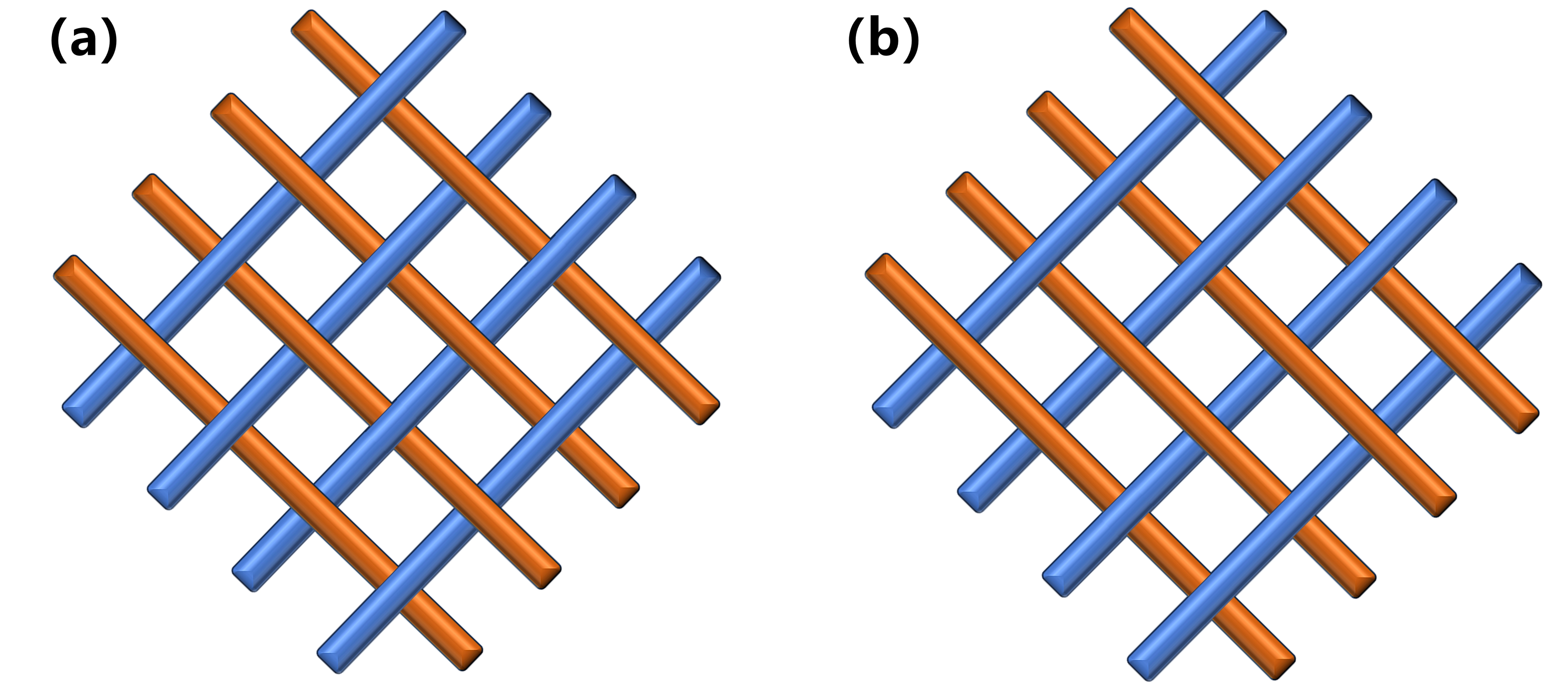
Table 1. Braiding parameters for different catheters and stents[1].
| Catheters | Stents | ||||||
| D (mm) | PPI | N | S | D (mm) | PPI | N | S |
| 1/3/5 | 60 | 16 | 1-2 | 6/8/10 | 100 | 48 | 1-2 |
| 60 | 16 | 1-1 | 100 | 48 | 1-1 | ||
| 60 | 32 | 1-2 | 100 | 96 | 1-2 | ||
| 90 | 16 | 1-2 | 150 | 48 | 1-2 | ||
| 90 | 16 | 1-1 | 150 | 48 | 1-1 | ||
| 90 | 32 | 1-2 | 150 | 96 | 1-2 | ||
| 120 | 16 | 1-2 | 200 | 48 | 1-2 | ||
| 120 | 16 | 1-1 | 200 | 48 | 1-1 | ||
| 120 | 32 | 1-2 | 200 | 96 | 1-2 | ||
PPI: points per inch.
2.2 Mechanical characterization of stents
After the braiding was completed, the braided stents needed to undergo a heat-setting process to ensure that the stents have maintained a stable shape and shape-memory properties. Based on preliminary investigations, the heat-setting temperature was set at 550 °C for 30 minutes. After air-cooling, the stents were demolded to yield the final products. The catheters and stents demonstrate uniform braiding structure meeting specifications, with the photo shown in Figure 2a,b,c) and Figure S1-6. The actual braiding angle and PPI of braided tubes with different parameters, shown in Table S1, confirming compliance with all specifications for the prepared samples.
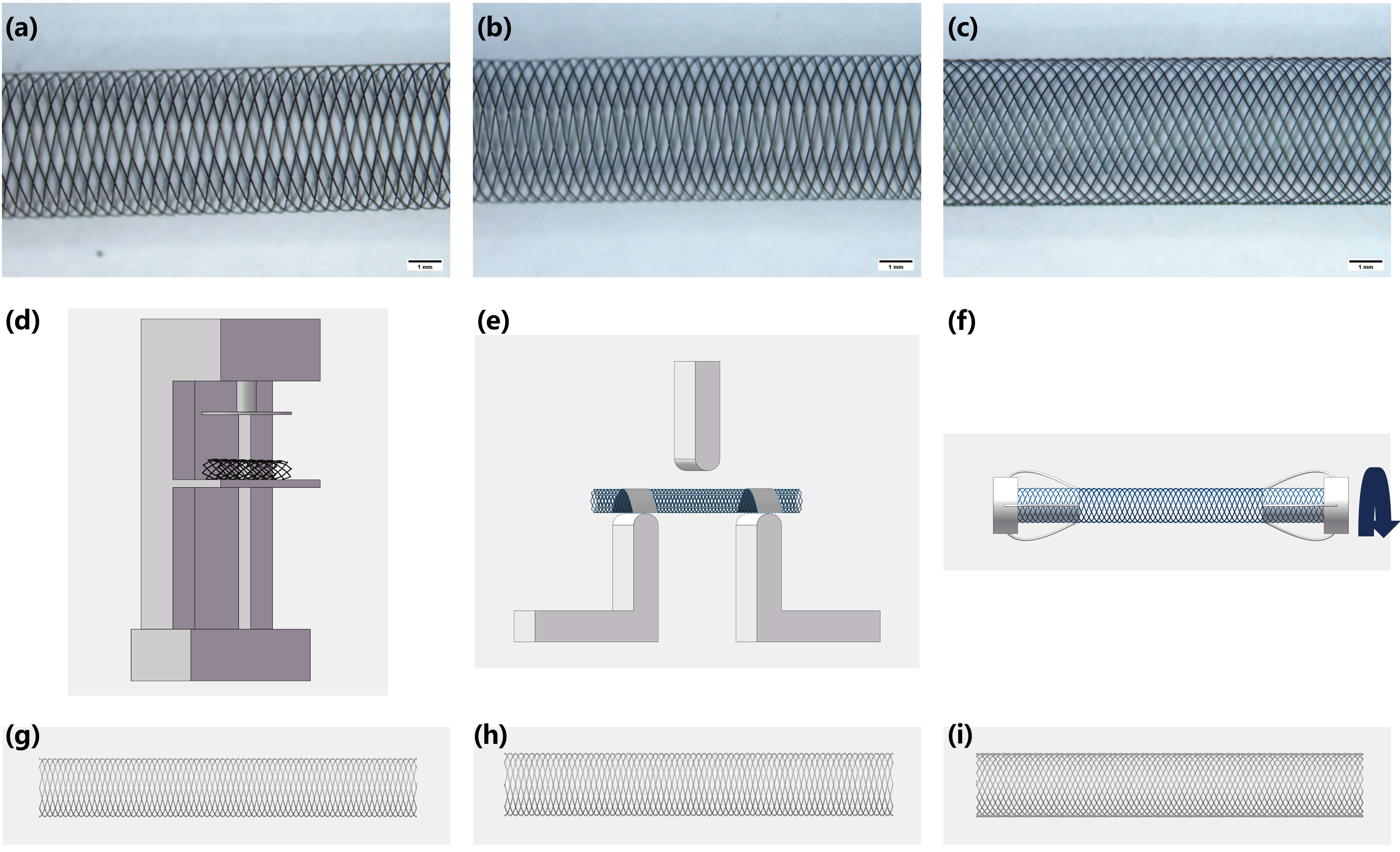
Figure 2. (a) 16/1-1 pattern stent (5 mm 60 PPI); (b) 16/1-2 pattern stent (5 mm 60 PPI); (c) 32/1-2 pattern stent (5 mm 60 PPI); (d) Schematic diagram of parallel plates compression tester; (e) Three-point bending test configuration; (f) Torsional testing setup; (g) 16/1-1 pattern stent model (5 mm 60 PPI); (h) 16/1-2 pattern stent model (5 mm 60 PPI); (i) 32/1-2 pattern stent model (5 mm 60 PPI). PPI: points per inch.
2.2.1 Compression resistance test
In accordance with ISO 25539-2 requirements, the radial strength of stents was evaluated using a parallel plate compression testing system (LLY-06D, Laizhou Digital Instrument Co. Ltd., Shandong, China), as illustrated in Figure 2d. Test specimens were cut to 30 mm lengths. The compression distance was set to 50 % of the specimen diameter. The compression and recovery speed were 5 mm/min, with a compression and recovery dwell time of 30 seconds.
2.2.2 Compression resistance test
A custom three-point bending fixture compliant with ASTM F2606-08 was designed and installed on the LLY-06D testing platform, as illustrated in Figure 2e.
After placing the stent on the lower compression head, both ends of the stent were secured with adhesive tape before testing. Specific parameters included: 14 mm span length for catheter specimens and 22 mm for stent specimens; 8 mm compression distance for catheters and 6 mm for stents; compression/recovery rates of 10 mm/min for braided catheters and 15 mm/min for braided stents.
2.2.3 Torsion test
Specimens (25 mm length for catheters; 30 mm for stents) were secured at both ends onto the mandrels of the torsion tester (LLY-19, Laizhou Digital Instrument Co. Ltd., Shandong, China), as illustrated in Figure 2f. The span was adjusted to 10 mm (catheters) or 15 mm (stents) to ensure the specimens could straighten naturally without axial force. Torsion angles were set to 20° (catheters) and 15° (stents). One end remained stationary while the other end was rotated around the mandrel axis at a rate of 6 °/min. The force variation during rotation was recorded, with maximum torsional force determined.
2.2.4 Statistical analysis
Statistical analysis was performed using one-way analysis of variance followed by Tukey’s post hoc test, as set in the Origin software (OriginLab Corp.). Each test (flat-plate compression, three-point bending, and torsion) was repeated five times per parameter, and the resulting data were analyzed for differences between groups. Significance was defined as follows: *p < 0.05, **p < 0.01, and ***p < 0.001. Error bars in the figures represent the standard deviation (SD).
2.3 Model establishment and boundary conditions for FEA
To balance the computational efficiency, we investigated braiding structure and wire count effects on mechanical properties at fixed PPI. The models of FEA were performed as follows: 5 mm diameter, 60 PPI catheters were selected for compression resistance test, and 3 mm diameter, 60 PPI catheters were selected for three-point bending and torsion tests.
2.3.1 Geometry modeling
Parametric equations derived from the mathematical braided stent model were implemented in SolidWorks 2023 to generate individual monofilament trajectory curves[29,30]. Each curve was swept along its 3D path to create cylindrical wire solids. Two monofilament models with opposing braiding directions were first constructed based on the equations, and the remaining filaments were efficiently generated using the circular pattern tool, significantly improving modeling efficiency. The complete models are shown in Figure 2g,h,i.
2.3.2 Boundary conditions for compression resistance test
Stent models (30 mm length) were imported into Abaqus CAE 2023 and assembled with upper/lower compression plates to form the FEA model (Figure S7a). The entities were three-dimensional deformable solids. The mechanical properties of nitinol wires, were determined via tensile testing conducted in accordance with ASTM F2516-2014, are provided in Table 2[2].
Table 2. The material parameters of the stents, plates and indenters[2].
| Plates/Indenters | Stents | |
| Density(g/cm3) | 7.8 | 6.45 |
| young's modulus (MPa) | 210,000 | / |
| Poisson’s ratio | 0.25 | 0.3 |
| Austenite’s young’s modulus (MPa) | / | 43,000 |
| Martensite’s young’s modulus (MPa) | / | 29,000 |
| Transformation strain | / | 0.0442 |
| Start of transformation loading (MPa) | / | 540 |
| End of transformation loading (MPa) | / | 540 |
| Start of transformation unloading (MPa) | / | 100 |
| End of transformation unloading (MPa) | / | 100 |
| Start of transformation in compression loading (MPa) | / | 540 |
A Dynamic Explicit analysis step was employed (time period: 0.01 s). The stent was meshed with C3D8I elements (size: 0.1), while compression plates used C3D10M elements (size: 1). The finite element mesh counts for braided stents in parallel plate compression simulation were 92,624 (16/1-1), 92,512 (16/1-2), and 99,136 (32/1-2) elements. A time step of 0.01 was selected after trial simulations, with the kinetic energy/internal energy ratio maintained below 0.05 to ensure quasi-static conditions. Reference points RP-1 and RP-2 were defined at the centroids of the lower and upper plates, respectively, with rigid body constraints coupling each plate to its reference point. Boundary conditions were configured as follows: the lower plate was fully fixed (U1 = U2 = U3 = UR1 = UR2 = UR3 = 0), and the upper plate was displacement-controlled (U1 = U3 = UR1 = UR2 = UR3 = 0; U2 = -x mm, where x represents half of the outer diameter of the braided stent model). General contact interaction was activated with a friction coefficient of 0.25.
2.3.3 Boundary conditions for three-point bending test
Stent models (25 mm length) were imported into Abaqus (Figure S7b). The entities were three-dimensional deformable solids.
A Dynamic Explicit analysis step (time period: 0.015) was implemented. The stent and cylindrical indenters were meshed with C3D8I elements (size: 0.1), while restraining plates used C3D10M elements (size: 1). For three-point bending simulations, the finite element mesh counts were 48,176 (16/1-1), 48,736 (16/1-2), and 56,320 (32/1-2) elements. A time step of 0.015 was selected after trial simulations to ensure the accuracy of the analysis. Reference points were defined at the centroids of the three indenters and two restraining plates, with rigid body constraints coupling each component to its reference point. Boundary conditions were configured as follows: the two lower indenters were fully fixed (U1 = U2 = U3 = UR1 = UR2 = UR3 = 0), while the upper indenter was subjected to a displacement constraint (U1 = U3 = UR1 = UR2 = UR3 = 0; U2 = -x mm, where x represents the downward displacement distance of the indenter). General contact interaction was activated with a friction coefficient of 0.25.
2.3.4 Boundary conditions for torsion test
Stent models (10 mm length) were assembled in Abaqus as shown in Figure S7c. The entities were three-dimensional deformable solids.
A Dynamic Explicit analysis step (time period: 0.07) was implemented. The stent was meshed with C3D8I elements (size: 0.1). For torsion simulations, the finite element mesh counts were 19,264 (16/1-1), 19,584 (16/1-2), and 22,656 (32/1-2) elements. A time step of 0.07 was selected after trial simulations to ensure the accuracy of the analysis. Reference points were defined at the centroids of both stent end-faces, with distributing coupling constraints applied between each reference point and its corresponding stent-end wire cross-sections. Boundary conditions were configured as follows: one reference point was fully fixed (U1 = U2 = U3 = UR1 = UR2 = UR3 = 0), while the other reference point was subjected to rotational constraints (U1 = U2 = U3 = UR1 = UR2 = 0; UR3 = x mm, where x represents the torsional angle). General contact interaction was activated with a friction coefficient of 0.25.
3. Results
3.1 Morphological characterization and WCC of catheters and stents
Nitinol alloy wire, the primary material for braided stents, is widely used in minimally invasive devices[31]. Heat-set nitinol stents can be compacted into delivery catheters and self-expand at target sites, with excellent mechanical properties for dilating narrowed tubular tissues, such as diseased vessels, esophagus, bile duct, etc.[32,33].
WCC, a critical braiding parameter, significantly affects stent mechanical performance[34,35]. According to the derivation formula of WCC, it exhibits a positive correlation with yarn width c, the number of yarns in a yarn group ns, the angle θ, and the radius of the mandrel rm, while showing a negative correlation with other braiding parameters such as take-up speed and convergence length.
As shown in Figure 3a,b, WCC is consistent between 1-over-1 and 1-over-2 braiding patterns at equal wire counts. WCC increases with PPI at fixed diameter, and decreases nonlinearly with expanding diameter at fixed PPI, with a diminishing attenuation rate at larger diameters.
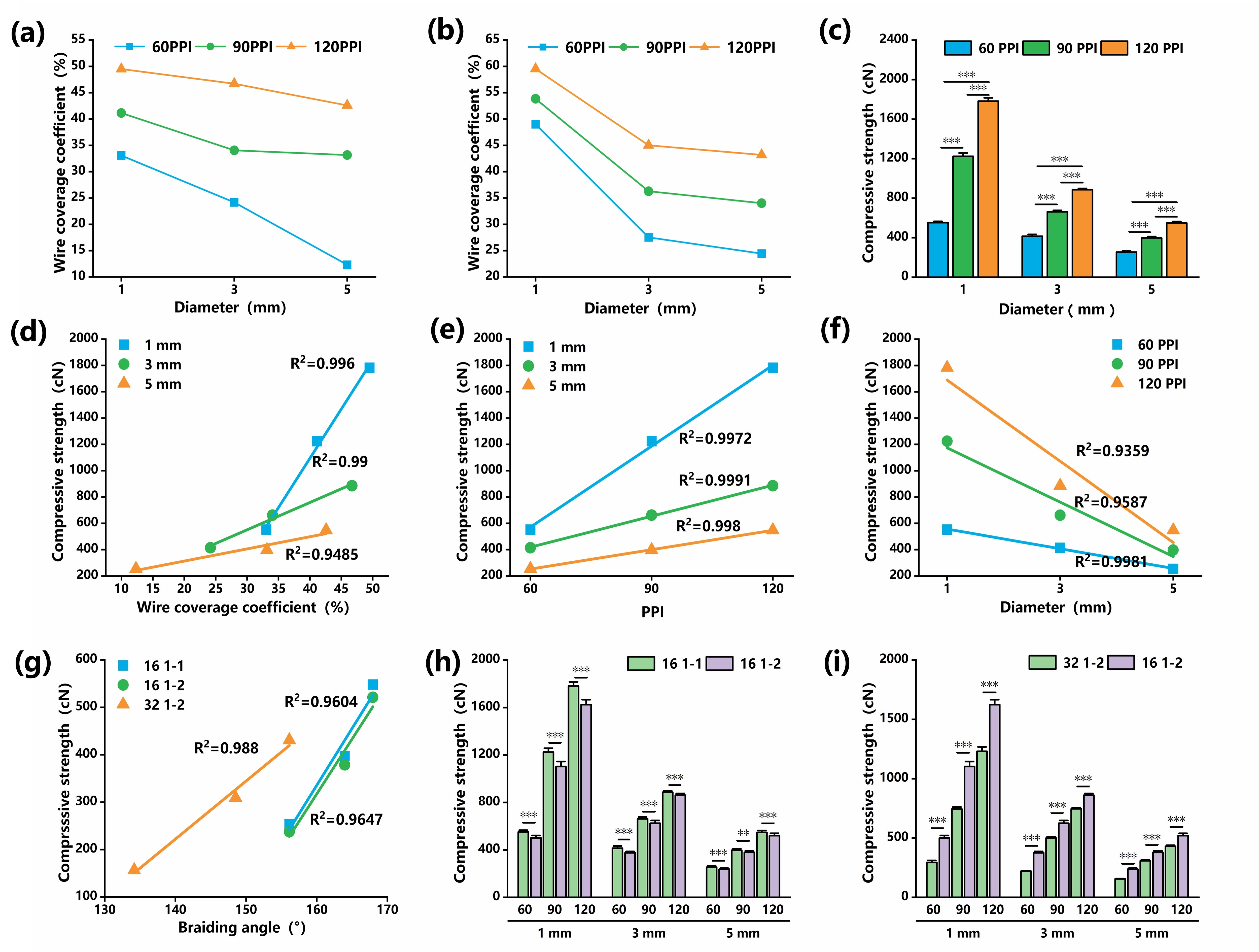
Figure 3. (a) WCC of 16/1-1 and 1-2 structure; (b) WCC of 32/1-2 structure; (c) Compressive strength of 16/1-1 structure; (d) Linear relationship between compressive strength and WCC for 16/1-1 catheters with different diameters; (e) Linear relationship between compressive strength and PPI for 16/1-1 catheters; (f) Linear relationship between compressive strength and diameter for 16/1-1 catheters; (g) Linear relationship between compressive strength and braiding angle for 5 mm catheters; (h) Effect of the number of wires on compressive strength; (i) Effect of the braiding structure on compressive strength. WCC: wire coverage coefficient.
3.2 Compression resistance test using parallel plates compression tester
Mechanical characterization reveals distinct compressive behavior patterns in braided devices. In Figure 3c, catheter compressive strength varies systematically with braiding configurations. Figure 3d demonstrates that for catheters of the same diameter, compressive strength increases approximately linearly with WCC, exhibiting strong linear correlation (R2 > 0.94). However, this WCC-strength relationship becomes non-systematic across varying diameters. Comparative analysis of 16/1-1 structures show similar compressive strength between 3 mm/60 PPI (414.57 ± 18.58 cN) and 5 mm/90 PPI (397.29 ± 13.55 cN) despite their WCC being different (24.17% vs. 33.17%). Analogous behavior occurs between 1 mm/60 PPI and 5 mm/120 PPI specimens. As illustrated in Figure S8, catheters and stents with other configurations exhibit similar patterns.
Figure 3e demonstrates a strong positive correlation between compressive strength and PPI. Holding other parameters constant, compressive strength increases approximately linearly with rising PPI (R2 > 0.99). For 1 mm diameter catheters (16/1-1), compressive strength escalates sharply with PPI, where 120 PPI yields 1782.32 ± 33.39 cN, 3.22 times greater than the 552.81 ± 12.73 cN at 60 PPI. For 5 mm diameter catheters, the increase is less pronounced, with 120 PPI yielding 548.09 ± 15.08 cN, 2.16 times higher than the 253.76 ± 10.67 cN at 60 PPI. Figure S9 confirms this fundamental trend across diverse catheter and stent architectures. Figure 3f demonstrates an inverse correlation between compressive strength and catheter diameter under constant parameters, where strength linearly decreases with increasing diameter (R2 > 0.93). For 120 PPI (16/1-1), compressive strength surges dramatically at smaller diameters: 1 mm specimens achieve 1782.32 ± 33.39 cN, 3.25 times higher than 5 mm (548.09 ± 15.08 cN). At 60 PPI, the same diameter reduction yields only a 2.18-fold increase (552.81 ± 12.73 cN at 1 mm and 253.76 ± 10.67 cN at 5 mm). Figure S10 confirms this fundamental trend across diverse catheter and stent architectures.
The braiding angles of different braided structures for both catheters and stents were calculated. Figure 3g reveals a linear correlation between catheter compressive strength and braiding angle (R2 > 0.96), where strength increases proportionally with braiding angle under constant parameters. However, braiding angle alone cannot fully determine compressive strength, as demonstrated by 5 mm diameter catheters: 32/1-2 (120 PPI) at 156.13° exhibit 430.71 ± 8.38 cN strength versus 16/1-2 (60 PPI) at 156.13° with only 237.81 ± 7.42 cN, a 44.79% strength reduction despite nearly identical angles. Figure S11 confirms this phenomenon across diverse catheter/stent configurations, showing significant compressive strength variations in structures with similar braiding angles. Figure 3h demonstrates divergent structural effects: For catheters, compressive strength is significantly higher in 1-1 structures compared to 1-2 (quantitative increase detailed in Table S2, where the 1-1 pattern yields a 7.42% greater average compressive strength versus 1-2).
Conversely, stents exhibit no statistically significant compressive strength variation between these braiding architectures. Figure 3i demonstrates the effect of wire count on compressive strength, revealing that compressive strength decreases as wire count increases. As quantified in Table S3, the 16-wire catheters exhibit 39.54% higher compressive strength on average than the 32-wire counterpart. This trend extends to braided stents, with 48-carrier stents achieving 15.35% greater compressive strength versus 96-carrier stents. This phenomenon is primarily attributed to the substantial decrease in braiding angle induced by higher wire counts, which consequently diminishes compressive strength.
3.3 Structure-property relationships of three-point bending strength
Figure 4a shows the bending strength of 16/1-1 braided catheters, while Figure 4b reveals that for 1 mm diameter catheters, bending resistance decreases linearly with increasing WCC. For 1 mm catheters, bending strength decreased linearly from 22.46 ± 1.08 cN (60 PPI) to 19.83 ± 0.66 cN (120 PPI), showing an 11.71% reduction. In contrast, 3 mm and 5 mm diameters exhibited linearly increasing resistance (R2 > 0.92), while stents showed stronger linear growth (R2 > 0.97). Notably, structural parameters dominated over minor WCC variations, when comparing 3 mm (34.05% WCC) and 5 mm (33.17% WCC) catheters at 60 PPI, the 5 mm variant demonstrated a 60.73% higher bending strength (4.42 ± 0.12 cN and 2.75 ± 0.16 cN). Figure 4c demonstrates a strong correlation between catheter bending strength and PPI. Holding other parameters constant, bending strength increased linearly with PPI (R2 > 0.95) across all diameters except 1 mm. For 16/1-1 catheters at 1 mm diameter, bending strength decreased with rising PPI. Conversely, at 3 mm and 5 mm diameters, bending strength at 60 PPI (3.97 ± 0.13 cN and 2.30 ± 0.12 cN, respectively) increased by 28.97% and 33.48% compared to that at 120 PPI. As shown in Figure S14, all catheters exhibit reduced bending strength with increasing PPI at 1 mm diameter during three-point bending. Conversely, stents, which have larger diameters, exhibit proportionally enhanced bending strength with increasing PPI.
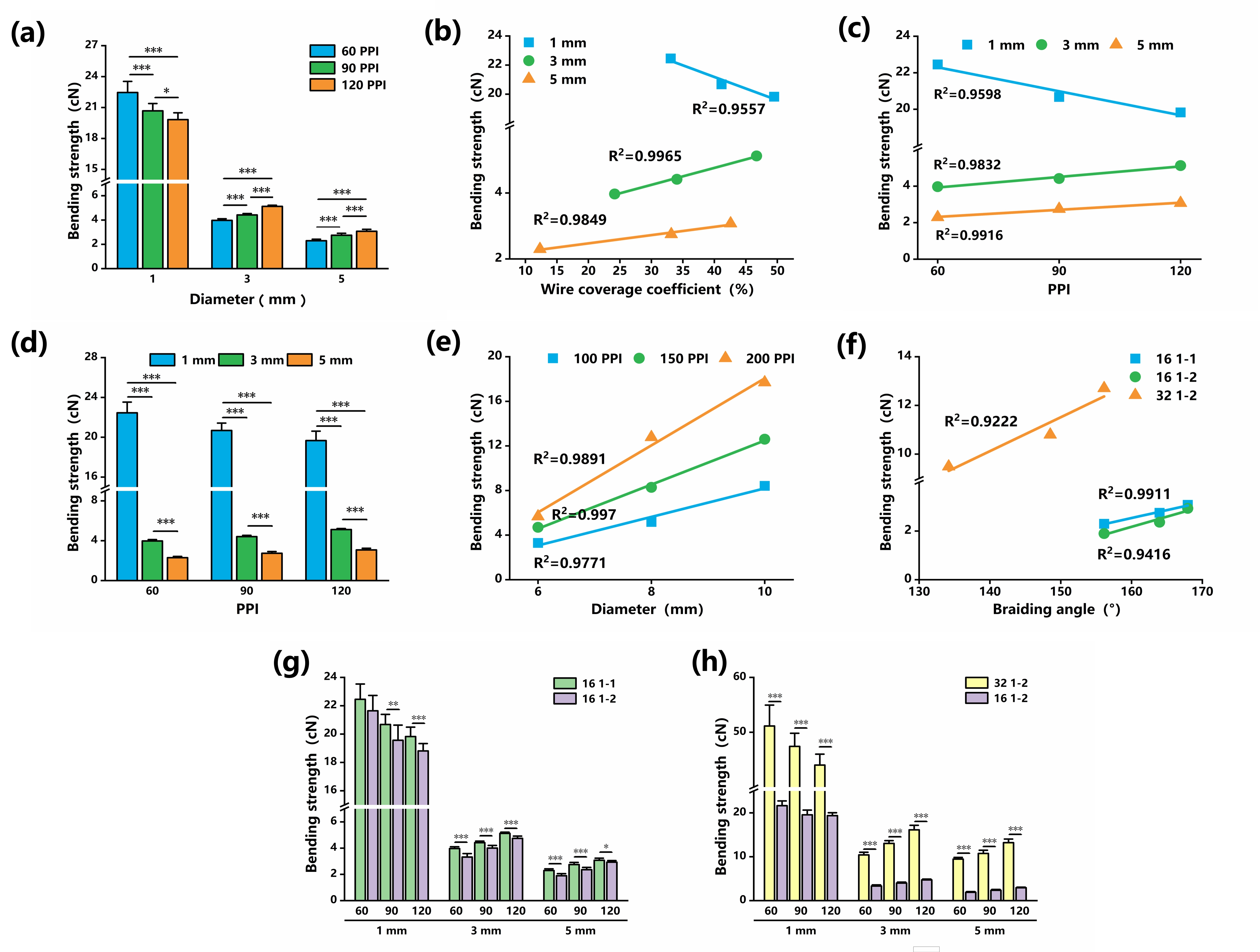
Figure 4. (a) Bending strength of 16/1-1 structure; (b) Linear relationship between bending strength and WCC for 16/1-1 catheters with different diameters; (c) Linear relationship between bending strength and PPI for 16/1-1 catheters; (d) Relationship between bending strength and diameter for 16/1-1 catheters; (e) Linear relationship between bending strength and diameter for 48/1-1 catheters; (f) Linear relationship between bending strength and braiding angle for 5 mm catheters; (g) Effect of the Braiding Structure on Bending Strength; (h) Effect of the number of wires on compressive strength. WCC: wire coverage coefficient.
Diameter exerts significant influence on the bending strength of braided tubes, particularly at smaller dimensions. As shown in Figure 4d, catheters demonstrate substantially higher bending strength at 1 mm diameter compared to 3 mm and 5 mm diameters. For 16/1-1 structures, the bending strength at 1 mm/60 PPI (22.46 ± 1.08 cN) exceeds that of 5 mm/60 PPI (2.30 ± 0.12 cN) by a factor of 9.77. In contrast, as shown in Figure 4e, stents exhibit less pronounced diameter dependence, showing a linear increase in bending resistance with larger diameters (R2 > 0.94). For 5 mm diameter catheters (Figure 4f), bending strength exhibits a strong linear relationship with braiding angle, increasing proportionally with higher angles (R2 > 0.92). Notably, all 1 mm diameter catheters demonstrate an inverse relationship, with bending strength decreasing linearly with increasing braiding angle. The 32/1-2 pattern showed the most pronounced decrease at 1 mm diameter (13.96% reduction from 51.14 ± 3.81 cN at 60 PPI to 44.00 ± 2.00 cN at 120 PPI). Figure S16 confirms this diameter-dependent trend across other configurations, with larger-diameter devices consistently showing increased bending strength at higher braiding angles.
Figure 4g delineates distinct structural effects: In catheters, the 1-1 structure exhibits marginally higher bending strength than the 1-2 structure (average +10.6%, see Table S4). Conversely, stents demonstrate profound structural influence, where the 1-1 structure yields a 35.35% greater average bending strength versus the 1-2 structure. Figure 4h further reveals filament count scalability: Bending strength increases significantly with wire count across both types. Catheters show a 243.69% average gain when doubling wires (16 to 32), while stents exhibit a more pronounced 294.86% enhancement (48 to 96).
3.4 Structure-property relationships of torsional strength
Figure 5a shows the torsional strength of 16/1-1 braided catheters, while Figure 5b delineates its inverse relationship with WCC for 1 mm diameters. Strength decreased linearly from 4.13 ± 0.21 cN (60 PPI) to 2.73 ± 0.14 cN (120 PPI), reflecting a 33.92% reduction. This contrasts with the positive linear correlation (R2 > 0.92) observed in 3 mm and 5 mm catheters. Crucially, at near-identical WCC (1 mm/60 PPI: 33.07% and 3 mm/90 PPI: 34.05%), torsional strength diverged by 47.22% (4.13 ± 0.21 cN and 2.18 ± 0.20 cN). Figure 5c demonstrates a strong correlation between torsional strength and PPI for 16/1-1 catheters. With other parameters held constant, torsional strength increases linearly with PPI (R2 > 0.94) across all diameters except 1 mm. At 1 mm, torsional strength decreases with rising PPI. Figure S19 confirms this inversion. 16/1-2 structures similarly exhibit reduced torsional strength at 1 mm diameter with increasing PPI, while all other configurations maintain positive linear correlations between torsional strength and PPI. Figure 5d and Figure S20 show that torsional strength of both catheters and stents decreases approximately linearly with increasing diameter (R2 > 0.9). Notably, 16-wire catheters exhibit significantly steeper strength reduction rates at 60 PPI compared to 90 and 120 PPI. For 1-1 and 1-2 structures, torsional strength decreases from 4.13 ± 0.21 cN and 3.23 ± 0.21 cN at 1 mm diameter to 1.06 ± 0.09 cN and 0.58 ± 0.07 cN at 5 mm diameter, representing reductions of 74.33% and 82.04% respectively. Exemplified by 5 mm catheters (Figure 5e), torsional strength demonstrates a positive linear correlation with braiding angle (R2 > 0.91), consistent with most catheters and stents (Figure S21). However, all 16-carrier 1 mm diameter catheters show inverse behavior. Torsional strength decreases linearly with increasing braiding angle. The 1-2 structure shows a 23.22% reduction from 3.23 ± 0.21 cN at 91.92° to 2.48 ± 0.2 cN at 127.78°, while the 1-1 structure experiences a more pronounced 33.90% decrease from 4.13 ± 0.21 cN to 2.73 ± 0.14 cN across identical angular increments.
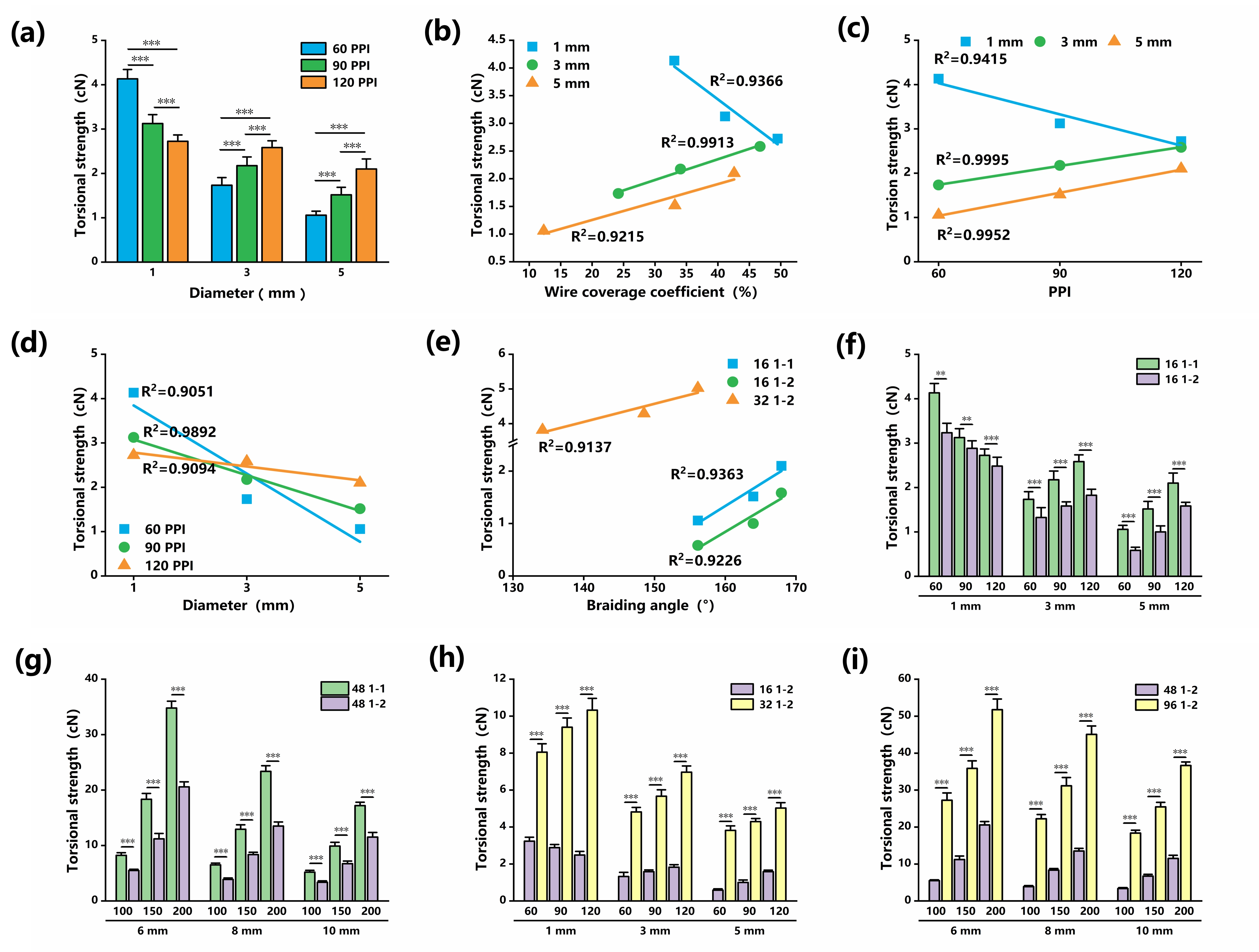
Figure 5. (a) Torsional strength of 16/1-1 structure; (b) Linear relationship between torsional strength and WCC for 16/1-1 catheters with different diameters; (c) Linear relationship between torsional strength and PPI for 16/1-1 catheters; (d) Linear relationship between torsional strength and diameter for 16/1-1 catheters; (e) Linear relationship between bending strength and braiding angle for 5 mm catheters; (f) Effect of the Braiding Structure on Bending Strength (catheters); (g) Effect of the Braiding Structure on Bending Strength (stents); (h) Effect of the number of wires on compressive strength (catheters); (i) Effect of the number of wires on compressive strength (stents). WCC: wire coverage coefficient; PPI: points per inch.
Figure 5f,g reveals distinct structural effects. For catheters, the 1-1 structure yields moderately higher torsional strength than the 1-2 structure (quantitative increases detailed in Table S6). In contrast, stents exhibit a significantly more pronounced difference. The 1-1 structure enhances strength by 58.68% on average compared to 1-2, versus merely 35.92% for catheters. Meanwhile, Figure 5h,i demonstrate that torsional strength increases substantially with wire count. Both catheters and stents show significant torsional resistance enhancement with additional wires. Specifically, 32 wires versus 16 increase strength by 288.92% on average, while 96 wires versus 48 yield a 294.7% average gain (Table S7).
3.5 FEA-driven mechanistic insights into braided structure mechanics
Building upon prior experimental findings which indicate that the mechanical behavior of braided tubes is predominantly governed by braiding topology (e.g., 1-1 vs. 1-2 structure) and wire count, the underlying mechanisms remain elusive. We therefore performed parametric FEA to decipher how these factors modulate mechanical performance and quantify their differential effects across distinct mechanical properties.
3.5.1 FEA of compression resistance test using parallel plates compression tester
Figure 6 reveals that under parallel plate compression, braided tubes develop high stress concentrations at plate-contact regions and lateral surfaces, with particularly extensive stress concentrations along the sidewalls. Comparative analysis of stress contour plots demonstrates minimal structural influence: the 1-1 and 1-2 structure exhibit virtually identical stress distributions. Maximum principal stress values show negligible difference (1-1: 719.6 MPa; 1-2: 730.2 MPa, a 1.48% variance), confirming that braiding architecture has no significant effect on global stress distribution.
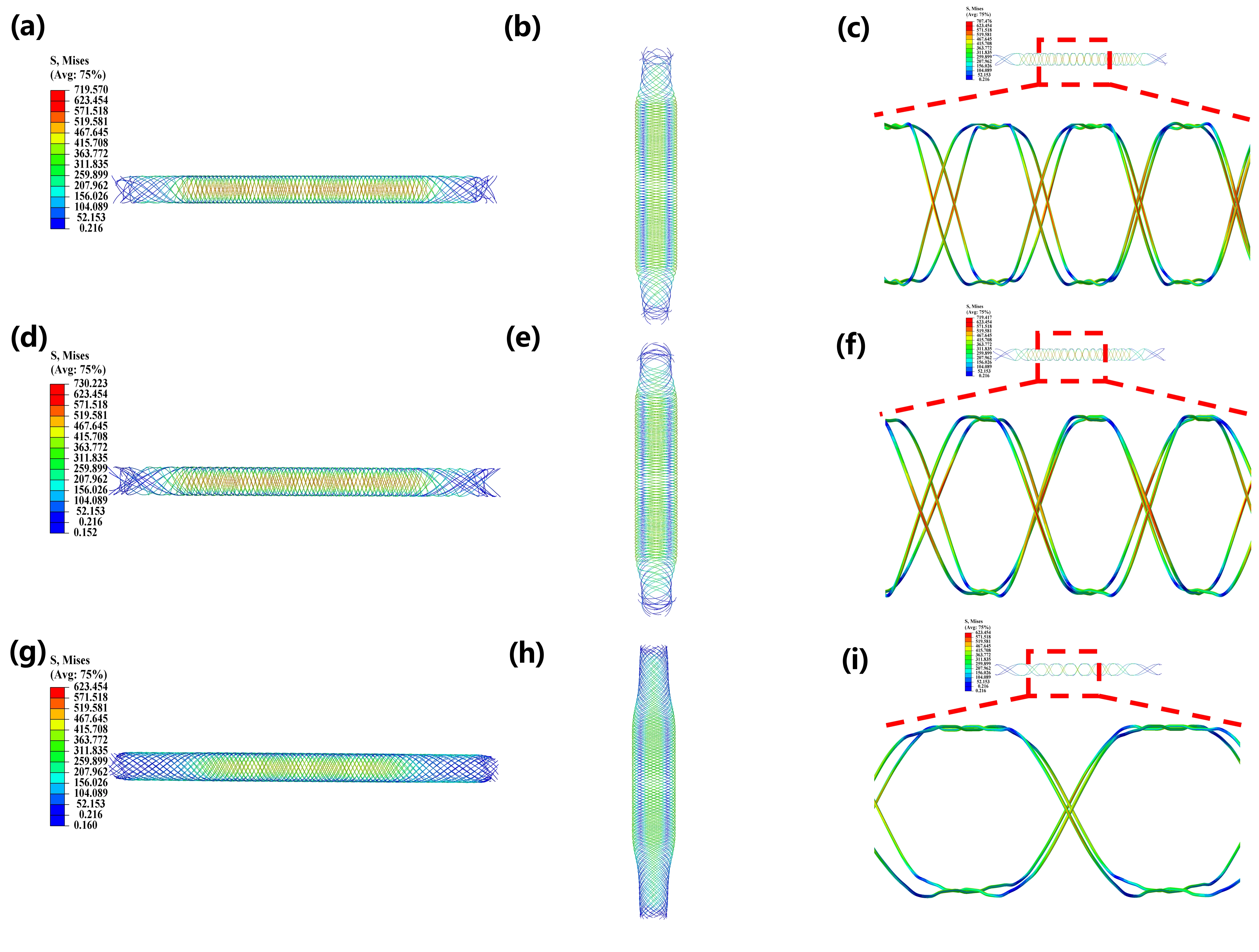
Figure 6. Von Mises stress contour plot under compression. (a) Lateral view of 16/1-1 (60 PPI); (b) Top view of 16/1-1 (60 PPI); (c) Localized stress contour plot in wires with magnified detail (16/1-1 60PPI); (d) Lateral view of 16/1-2 (60 PPI); (e) Top view of 16/1-2 (60 PPI); (f) Localized stress contour plot in wires with magnified detail (16/1-2 60PPI); (g) Lateral view of 32/1-2 (60 PPI); (h) Top view of 32/1-2 (60 PPI); (i) Localized Von Mises stress contour plot in wires with magnified detail (32/1-2 60PPI). PPI: points per inch.
Comparative stress contour analysis in Figure 6a,d,g) reveals that 32-wire braided tubes exhibit 14.7% lower peak stress (623.5 MPa and 730.2 MPa in 16-wire configurations) with more uniform distribution and enhanced structural stability, forming characteristic elliptical deformation profiles during compression, as shown in Figure 6b,e,h. Conversely, 16-wire tubes demonstrate localized high-stress concentrations along lateral edges, which explains their relatively higher compressive strength. Analysis of individual wire stress in Figure 6c,f,i reveals consistent concentration patterns: maximum stresses occur at compression plate interfaces and bending lateral surfaces, particularly at wire crossover points. The 32-wire catheter’s higher wire density and smaller braiding angle enable superior stress distribution, reducing individual wire stress by 18-22% compared to 16-wire structures through enhanced load-sharing mechanisms. As shown in the Figure S22a,b, these differences in stress distribution are the same as the variations in compressive strength. The 1-1 structure exhibited a higher compressive strength than the 1-2 structure. When comparing different wire counts in the same structure, the 16-wire configuration showed a markedly higher compressive strength than the 32-wire configuration.
3.5.2 FEA of three-point bending and torsional strength
The three-point bending simulation results in Figure 7a,b,c reveal differences in stress distribution characteristics between the two structural configurations. The 1-1 structure demonstrates a more extensive stress propagation area with a 2.8% higher peak stress value (172.575 MPa vs. 167.885 MPa in the 1-2 structure). This broader stress distribution, coupled with the involvement of more wire elements in load-bearing, contributes to the enhanced bending resistance observed in the 1-1 configuration. FEA of braided tube structures reveals superior mechanical performance in 32-wire configurations compared to 16-wire under three-point bending. Specifically, the 32-wire tubes exhibit a 145% higher peak von Mises stress (411.675 MPa and 167.885 MPa) accompanied by both greater wire participation in load transfer and expanded high-stress region volume fraction. Individual wire stress analysis reveals significantly higher stress concentrations at crossover points in 1-1 structures compared to 1-2 structures during three-point bending, as shown in Figure 7d,e,f. All three configurations show pronounced stress accumulation at indenter contact zones, with 32/1--2 structures exhibiting exceptionally high interfacial stresses. As shown in the Figure S22c,d, these differences in stress distribution correspond to the variations in bending strength. The 1-1 structure exhibited significantly higher bending strength than the 1-2 structure at the same wire count. When comparing different wire counts in the same structure, the 32-wire configuration showed markedly higher bending strength than the 16-wire configuration.
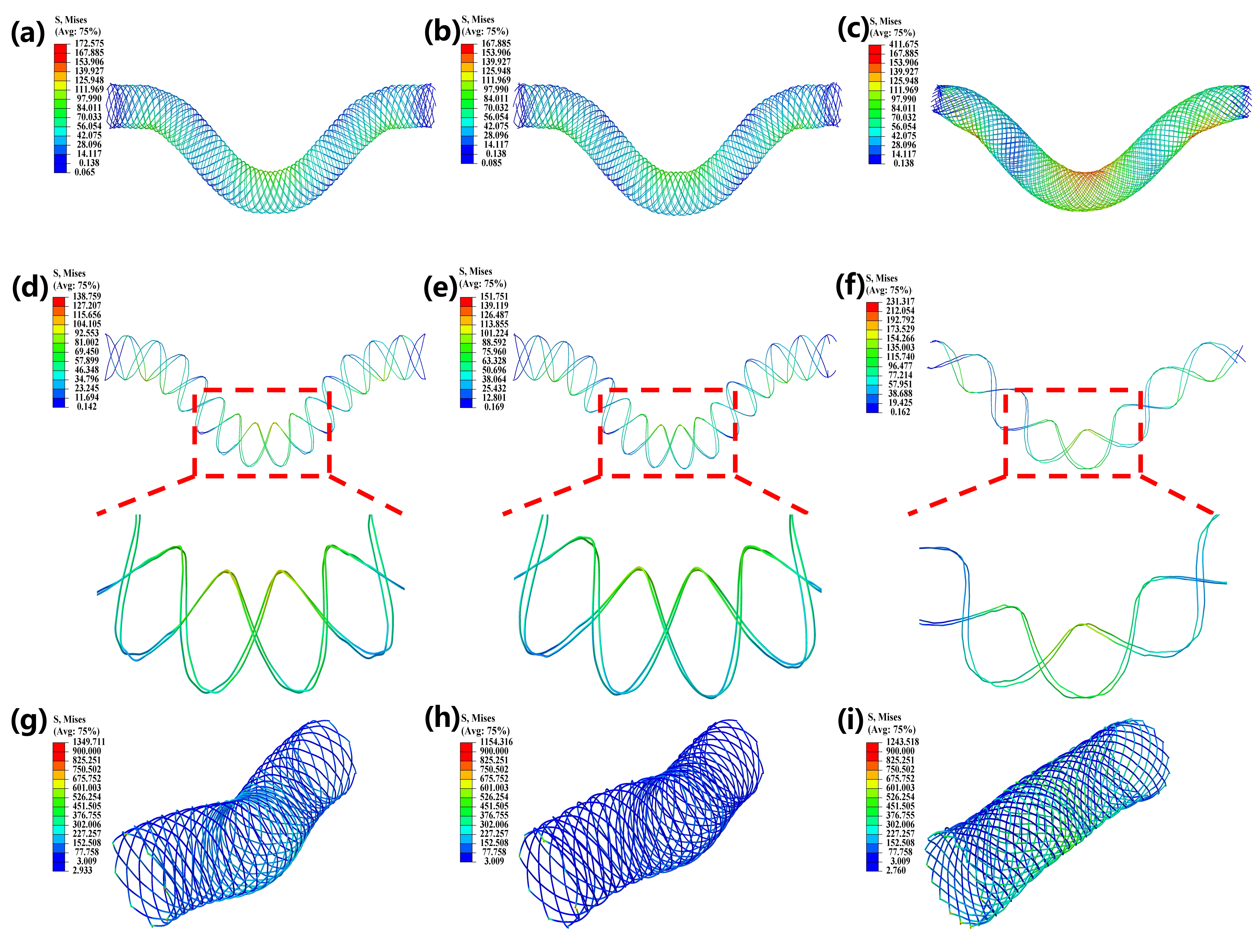
Figure 7. Von Mises stress contour plot. (a) 16/1-1 (60 PPI) through three-point bending; (b) 16/1-2 (60 PPI) through three-point bending; (c) 32/1-2 (60 PPI) through three-point bending; (d) Localized contour plot in wires with magnified detail (16/1-1 60PPI); (e) Localized contour plot in wires with magnified detail (16/1-2 60PPI); (f) Localized contour plot in wires with magnified detail (32/1-2 60PPI); (g) 16/1-1 (60 PPI) through torsion; (h) 16/1-2 (60 PPI) through torsion; (i) 32/1-2 (60 PPI) through torsion. PPI: points per inch.
Analysis of the torsion stress contour plots in Figure 7g,i reveal that the 1-1 structure generates stress distribution across a significantly wider area compared to the 1-2 structure. This structural arrangement subjects a broader range of wires to elevated stress loading while concurrently achieving a 16.9% higher peak stress (1,349.711 MPa and 1,154.316 MPa). These combined characteristics (broader stress propagation and greater peak stress magnitude) directly enhance the torsional resistance of the 1-1 braiding architecture.
For braided tubes with varying wire densities, 32-wire configurations demonstrate substantially superior mechanical performance. These tubes exhibit both higher peak stress values and more load-bearing wires than the 16-wire tubes. This enhancement of mechanical properties was characterized by amplified stress levels and more extensive load-sharing among wires, which explains the significantly higher torsional strength observed in 32-wire braided tubes.
As shown in the Figure S22e,f, these differences in stress distribution correspond to the variations in torsional strength. The 1-1 structure exhibited significantly higher torsional strength than the 1-2 structure at the same wire count. When comparing different wire counts in the same structure, the 32-wire configuration showed markedly higher torsional strength than the 16-wire configuration.
4. Discussion
Regarding the mechanical properties of braided stents, previous research have predominantly focused on the influence of single or a limited number of geometric parameters on stent performance, particularly compression behavior. For example, Liu et al.[3], Ciara et al.[20], Kim et al.[23], and Duda et al.[10] have conducted experimental tests or FEA on the compressive properties of braided stents with different materials and structures. These studies consistently indicate that the structural parameters of braided stents affect their compression performance. However, most existing research remains qualitative within a relatively narrow parameter range, lacking systematic quantitative investigations. Rebelo et al.[36] also investigated the influence of process parameters on braided stents and identified certain trends. However, their study only discussed the effects of different materials, diameters, and braiding angles, without conducting a systematic analysis of all parameters. Moreover, they did not employ FEA to explore the mechanistic basis behind their findings. Similarly, while some studies have addressed the impact of braiding structure on tensile or other properties, there is a general absence of systematic examination of bending and, especially, torsional performance[25-27,37]. Comprehensive studies simultaneously correlating multiple key parameters with various mechanical properties are even scarcer. In contrast, this study systematically and quantitatively correlated six critical parameters, PPI, braiding angle, WCC, diameter, braiding structure, and wire count, with three core clinically relevant mechanical properties of stents: compression, bending, and torsion. This approach has shown correlation models with high linearity (R2 ≥ 0.90).
The compression, bending, and torsional performance of stents are three crucial metrics for evaluating their quality. Due to differences in the physiological structure of lumens in various parts of the human body, the performance of stents applied to different locations requires a balance among these three properties. After implantation, the most critical function of a stent is to expand the narrowed lumen, maintaining its tubular structure and ensuring lumen patency under the compressive forces. Stents with insufficient radial strength may not conform well to the vessel wall after deployment, increasing the risk of migration within the vessel, while stents with excessive compressive strength may damage the vessel wall, leading to vessel dissection or excessive intimal hyperplasia. Therefore, designing an appropriate radial support performance is a key focus in stent development. In addition to sufficient radial support, stents also require a certain degree of axial flexibility to navigate through tortuous human vessels and reach the lesion site, while maintaining good lumen patency during bending. Simultaneously, when subjected to torsional forces within the body, the stent must ensure lumen openness while minimizing torsional stress on the vessel wall to reduce vascular injury. Currently, braided stents are primarily used in clinical applications such as cerebral blood flow diverters, lower limb arterial stenosis, ureteral strictures, and biliary strictures, owing to their advantages such as excellent flexibility, good wall apposition, strong kink resistance, and retrievability. The parameter-performance quantitative relationships established in this study enable engineers to directly predict stent behavior based on manufacturing specifications, significantly shortening the trial-and-error cycle and reducing development costs. In particular, this research provides a critical design framework and parameter selection guide for stent design in complex lesions, such as aneurysms requiring both kink resistance and high radial strength.
Currently, the relatively low resistance to radial compression of braided stents compared to those manufactured by other processes is one of the main factors limiting their application in other areas. Based on the linear relationship between braiding parameters and compression strength identified in this study, it can be concluded that to enhance the compression performance of braided stents, measures such as increasing PPI, braiding angle, and WCC can be adopted to improve their compression resistance. This result is consistent with the conclusions of most existing studies[38]. Alternatively, the linear relationship established in the study can be utilized to directly determine the range of braiding parameters once the desired compression strength is specified, thereby significantly saving time. Additionally, since stents with smaller diameters exhibit better compression resistance than those with larger diameters, selecting a stent with a smaller diameter is advisable when conditions permit. Similarly, Qiu et al. and Feng et al. also found that, with all other parameters kept constant, the partial compressive force decreases as the stent diameter increases. However, this diameter-dependent effect diminishes with increasing stent porosity[19,39-41]. The 1-1 and 1-2 structures have been shown to exhibit no significant difference in compression resistance.
Generally, we expect the bending strength and torsional strength of braided stents to remain at relatively low levels. The ease of bending and favorable torsional performance of braided stents are also key advantages driving their widespread application. Many studies have reported similar trends in the bending and torsional properties of braided stents to those observed in this work[39]. Zhao et al. comprehensively investigated the mechanical properties of braided stents. Similarly, they found that higher wire density leads to greater bending stress, and increasing the number of braided wires enhances radial compressive support while slightly reducing bending flexibility. Their study also confirmed a trade-off between radial support and structural compliance. Similarly, Ubachs et al. drew consistent conclusions[42]. Single-parameter optimization cannot achieve high structural strength and excellent flexibility simultaneously, and comprehensive coupling analysis of multiple mechanical performances is therefore required. However, in-depth discussion and further quantitative analysis were lacking in their work[43]. However, few studies have comprehensively investigated multiple mechanical performances and systematically analyzed the overall mechanical regulation mechanisms of braided stents. Studies have found that for most parameters, improving compression strength tends to concurrently increase bending and torsional strength, which may have adverse effects on stent performance. It can be observed that there exists a trade-off between the compression performance and the bending/torsional performance of braided stents. To enhance bending and torsional performance without compromising compression strength, the 1-2 structure can be selected. Its advantages in facilitating bending and torsion provide theoretical support for its application in tortuous vascular pathways.
Although this study has shown meaningful findings, several limitations remain. The current shortcomings include the experimental sample size (54 configurations), which, does not fully cover a more extensive range of parameters. Additionally, static in vitro testing cannot fully replicate the dynamic mechanical environment within the body, such as pulsatile pressure and cyclic bending. However, due to the complexity of simulating in vivo dynamic conditions and the challenges in fully controlling material and process variations at the laboratory scale, it is necessary to establish dynamic testing platforms that more closely mimic physiological conditions, conduct experiments with a wider range of parameters, and perform more prolonged explorations under more precisely controlled process conditions to obtain comprehensive performance data that better aligns with clinical reality. The reduction in bending flexibility with increasing PPI in 1 mm catheter-mounted stents is a counterintuitive finding. Detailed stress distribution analysis across PPI levels would clarify this behavior, and this mechanistic investigation is identified as a key direction for future work. Since the primary objective of this study is to establish quantitative relationships between braiding parameters and core mechanical properties, providing a key theoretical predictive tool for stent design, the current results still hold significant engineering value for shortening development cycles and guiding parameter optimization. In the future, we will continue to conduct in-depth research on the performance of stents under dynamic mechanical environments, long-term durability assessments, and personalized parameter design based on clinical lesion morphology.
5. Conclusions
This study systematically investigated the influence of geometric parameters (PPI, braiding angle, WCC, diameter, and braiding structure) on the mechanical performance of braided nitinol stents through combined FEA and in vitro experiments (compression resistance, bending flexibility, and torsional stability). PPI, braiding angle, WCC, and braiding diameter exhibited high linearity in their effects on the mechanical properties of both catheters and stents braided tubes, and all exhibit high linearity (≥ 90%). This linear relationship provides a guideline for engineers to predict and tailor the mechanical performance of stents based on their specific geometric configurations. The 1-1 braiding architecture exhibited greater bending/torsional resistance compared to 1-2 patterns. The number of wires had distinct effects on different mechanical properties. Under identical braiding structures and PPI, increasing the number of wires significantly enhanced the bending resistance and torsional strength of the stents, but led to a decrease in compressive strength.
In summary, this work establishes a mechanistic framework linking braiding parameters to stent functionality. By bridging engineering principles with clinical requirements, it lays the groundwork for next-generation endovascular devices that balance mechanical robustness with anatomical adaptability.
Supplementary materials
The supplementary material for this article is available at: Supplementary materials.
Authors contribution
Yu Y: Data curation, formal analysis, validation, visualization, writing-original draft.
Qiao J, Zhao W: Validation, data curation.
Zhao F: Conceptualization, methodology, writing-review & editing.
Lin J: Project administration.
Wang F: Funding acquisition, resources.
Wang L: Project administration, supervision, writing-review & editing.
Conflicts of interest
Fan Zhao is a Youth Editorial Board Member of BME Horizon. The other authors declare no conflicts of interest.
Ethical approval
Not applicable.
Consent to participate
Not applicable.
Consent for publication
Not applicable.
Availability of data and materials
The data and materials could be obtained from the corresponding author.
Funding
The authors acknowledge the research facilities supported by the Fundamental Research Funds for the Central Universities (Grant No. 2232024G-01), National Natural Science Foundation of China (Grant No.52303310), Donghua University-Guan Bo China Machinery Collaborative Innovation Center (Grant No. 0316HX101230762), and the Fundamental Research Project of CNTAC (Grant No. 21Q10107).
Copyright
© The Author(s) 2026.
References
-
1. Reorowicz P, Tyfa Z, Obidowski D, Wiśniewski K, Stefańczyk L, Jóźwik K, et al. Blood flow through the fusiform aneurysm treated with the Flow Diverter stent–Numerical investigations. Biocybern Biomed Eng. 2022;42(1):375-390.[DOI]
-
3. Liu X, Tao H, Li C, Lin J, Guan G, Wang F, et al. Effect of NiTi parameters on the mechanical properties of integrated braided stents. Text Res J. 2023;93(3-4):701-712.[DOI]
-
6. McIntee BE. The wallstent endoprosthesis. Gastrointest Endosc Clin N Am. 1999;9(3):373-381.[PubMed]
-
7. Sousa AM, Amaro AM, Piedade AP. Structural design optimization through finite element analysis of additive manufactured bioresorbable polymeric stents. Mater Today Chem. 2024;36:101972.[DOI]
-
14. Yang N, Huang W, Lin J, Chen Y, Wu Z, Jiang Y, et al. Stable and integrated nanocellulose-covered stents via in situ microbial synthesis. Adv Funct Mater. 2025;35(34):2415272.[DOI]
-
15. Xue W, Lin J, Wang F, Li Q, Wang L. Design and mechanical behaviors of sutureless prototype composite nitinol stent-grafts. Text Res J. 2018;88(13):1517-1530.[DOI]
-
16. Liu G, Zhang P, Wang W, Yang J. Study on braiding parameters of braiding nerve conduit. J Donghua Univ Nat Sci. 2003;29(6):5.[DOI]
-
18. Li C, Wang X, Zhao F, Wang F, Ting Z, Wang L. Modeling of braiding parameter impact on pore size and porosity in a tubular braiding fabric. E Polym. 2017;17(3):221-226.[DOI]
-
21. Shang Z, Ma J. Bending stiffness characterization of braided stent using spring-based theoretical formula. Arch Appl Mech. 2023;93(3):947-960.[DOI]
-
24. Boris D, Xavier L, Damien S. The tensile behaviour of biaxial and triaxial braided fabrics. J Ind Text. 2018;47(8):2184-2204.[DOI]
-
25. Jedda H, Ben Abdessalem S, Ragoubi M, Sakli F. Contribution to the optimisation of artificial ligament mechanical properties. J Text Inst. 2008;99(3):273-280.[DOI]
-
26. Lu X, Zhao S, Chen W, Xie H, Teng J, Ren L, et al. Bioinspired multilayer braided structure with controllable nonlinear mechanical properties for artificial ligaments. Mater Des. 2024;241:112976.[DOI]
-
27. Xiao S, Lanceron C, Wang P, Soulat D, Gao H. Mechanical and thermal behaviors of ultra-high molecular weight polyethylene triaxial braids: The influence of structural parameters. Text Res J. 2019;89(16):3362-3373.[DOI]
-
29. Alpyildiz T. 3D geometrical modelling of tubular braids. Text Res J. 2012;82(5):443-453.[DOI]
-
30. Rawal A, Gupta S, Saraswat H, Sibal A. Geometrical modeling of near-net shape braided preforms. Text Res J. 2015;85(10):1055-1064.[DOI]
-
32. Wei L, Chen N, Yang H, Zheng Z, Dong N, Guo H, et al. The data of Chinese minimally invasive cardiovascular surgery in 2019. Chin J Clin Thorac Cardiovasc Surg. 2019;28(2):149-153. Chinese.[DOI]
-
34. Heieck F, Hermann F, Middendorf P, Schladitz K. Influence of the cover factor of 2D biaxial and triaxial braided carbon composites on their in-plane mechanical properties. Compos Struct. 2017;163:114-122.[DOI]
-
36. Rebelo R, Vila N, Fangueiro R, Carvalho S, Rana S. Influence of design parameters on the mechanical behavior and porosity of braided fibrous stents. Mater Des. 2015;86:237-247.[DOI]
-
37. Zhu DM, Du Y, Lu GY, Cheng Z. Mechanical behavior of a new stent with negative poisson’s ratio: The influence of geometric parameters. J Mech Med Biol. 2024;24(6):2350108.[DOI]
-
38. Liu M, Tian Y, Cheng J, Zhang Y, Zhao G, Ni Z. Mixed-braided stent: An effective way to improve comprehensive mechanical properties of poly (L-lactic acid) self-expandable braided stent. J Mech Behav Biomed Mater. 2022;128:105123.[DOI]
Copyright
© The Author(s) 2026. This is an Open Access article licensed under a Creative Commons Attribution 4.0 International License (https://creativecommons.org/licenses/by/4.0/), which permits unrestricted use, sharing, adaptation, distribution and reproduction in any medium or format, for any purpose, even commercially, as long as you give appropriate credit to the original author(s) and the source, provide a link to the Creative Commons license, and indicate if changes were made.
Publisher’s Note
Science Exploration remains a neutral stance on jurisdictional claims in published
maps
and institutional affiliations. The views expressed in this article are solely those
of
the author(s) and do not reflect the opinions of the Editors or the publisher.
Share And Cite


Science Exploration Style
Yu Y, Qiao J, Zhao F, Zhao W, Lin J, Wang F, et al. Optimizing mechanical properties of braided nitinol stents through geometric parameter engineering: Insights from experiments and finite element analysis. BME Horiz. 2026;4:202610. https://doi.org/10.70401/bmeh.2026.0027
Tips
Copy completed.
Submit a Manuscript
Author Instructions
Cite this Article
Article Metrics
0
View
0
Download
Cited
Article Updates

 Get citation
Science Exploration Style

Yu Y, Qiao J, Zhao F, Zhao W, Lin J, Wang F, et al. Optimizing mechanical properties of braided nitinol stents through geometric parameter engineering: Insights from experiments and finite element analysis. BME Horiz. 2026;4:202610. https://doi.org/10.70401/bmeh.2026.0027
copy
Share Link
copy
Subscribe